Calculating the Voltage Drop in the I/O Power Supply
Voltage drop occurs in the CPU Units and NX Units due to the contact resistance at the points where
Units are connected to each other. Design the I/O power supply system to maintain the voltage specifi-
cations of the NX Unit I/O circuits and connected external devices even if the voltage of the I/O power
supply drops.
As shown in the following table, the voltage drop per Unit depends on the total current consumption
from the I/O power supply
.
Total current consumption from the I/O
power supply
Voltage drop per Unit
4 A 0.08 V
3 A 0.06 V
2 A 0.04 V
1 A 0.02 V
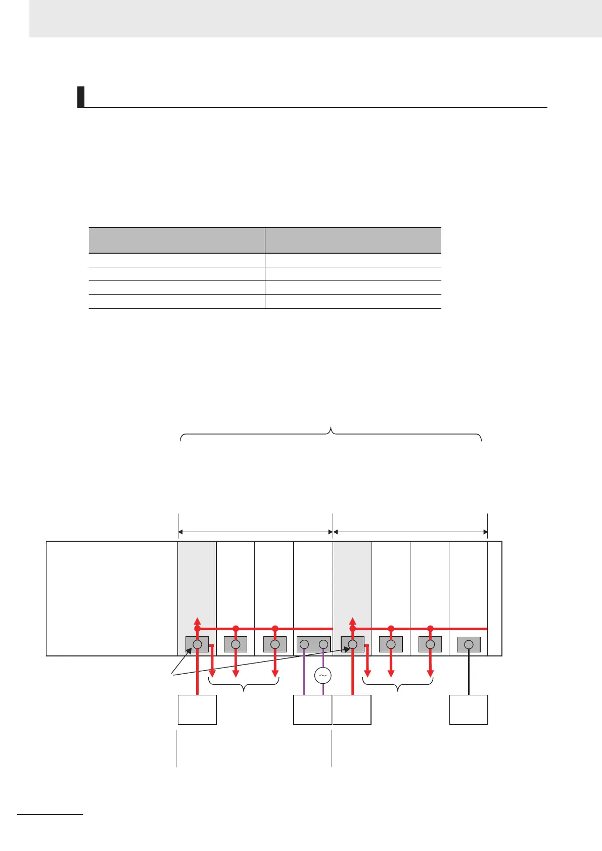
The following is a calculation example of the I/O power supply range applicable to the additional I/O
power supply unit that is located on the right side of CPU Unit based on a unit configuration example
shown below
. You can also use the same calculation procedure to calculate the I/O power supply
range after you add more I/O power supply units in addition to the first one.
Example:
NX-series NX1P2 CPU Unit
a. Total current consumption from I/O power
supply is 4 A or less
(NX Units with the supply from external
source or no supply are excluded from
calculation)
b. The voltage drop in the I/O power supply is
within the voltage specifications of the I/O
circuits of the NX Units and the connected
external devices.
Additional
I/O Power
Supply
Unit 1
NX Unit
(no
supply)
Additional
I/O Power
Supply
Unit 2
NX Unit
(supply
from
the NX
bus)
NX Unit
(supply
from
the NX
bus)
NX Unit
(supply
from
the NX
bus)
NX Unit
(supply
from
the NX
bus)
NX Unit
(supply
from
external
source)
•
When NX Units that require supply
from the NX bus are on the CPU Rack
•
When it exceeds the maximum I/O power supply
current, 4 A
•
When the I/O power supply voltage drops severely
•
When separating the I/O power supply
8 max.
I/O
power
supply
I/O
power
supply
External
device
To external
devices
To external
devices
End Cover
I/O power supply terminals
External
device
I/O power
supply
(DC)
I/O power
supply
(DC)
4 Designing the Power Supply System
4-18
NX-series NX1P2 CPU Unit Hardware User’s Manual (W578)
 Loading...


