I
ON
= (V
CC
− V
R
- 1.5 [internal residual voltage of DC input]) / R
IN
When I
ON
is smaller than I
OUT
(min), connect a bleeder resistor R. The bleeder resistor constant
can be calculated as follows:
R ≤ (V
CC
− V
R
) / (I
OUT
(min) − I
ON
)
Power W of bleeder resistor
≥ (V
CC
− V
R
)
2
/ R × 4 [allowable margin]
V
CC
: Input voltage of DC input
V
R
: Sensor's output residual voltage
I
ON
: Input current of DC input
I
OUT
: Sensor control current (load current)
R
IN
: Input resistor of DC input
(c) Relation between OFF current of the DC input and sensor leakage current
I
OFF
≥ I
leak
When I
leak
is greater than I
OFF
, connect a bleeder resistor R.
Use the following equation to calculate the bleeder resistance constant.
R ≤ R
IN
× V
OFF
/ (I
leak
× R
IN
− V
OFF
)
Power W of bleeder resistor ≥ (V
CC
− V
R
)
2
/ R × 4 [allowable margin]
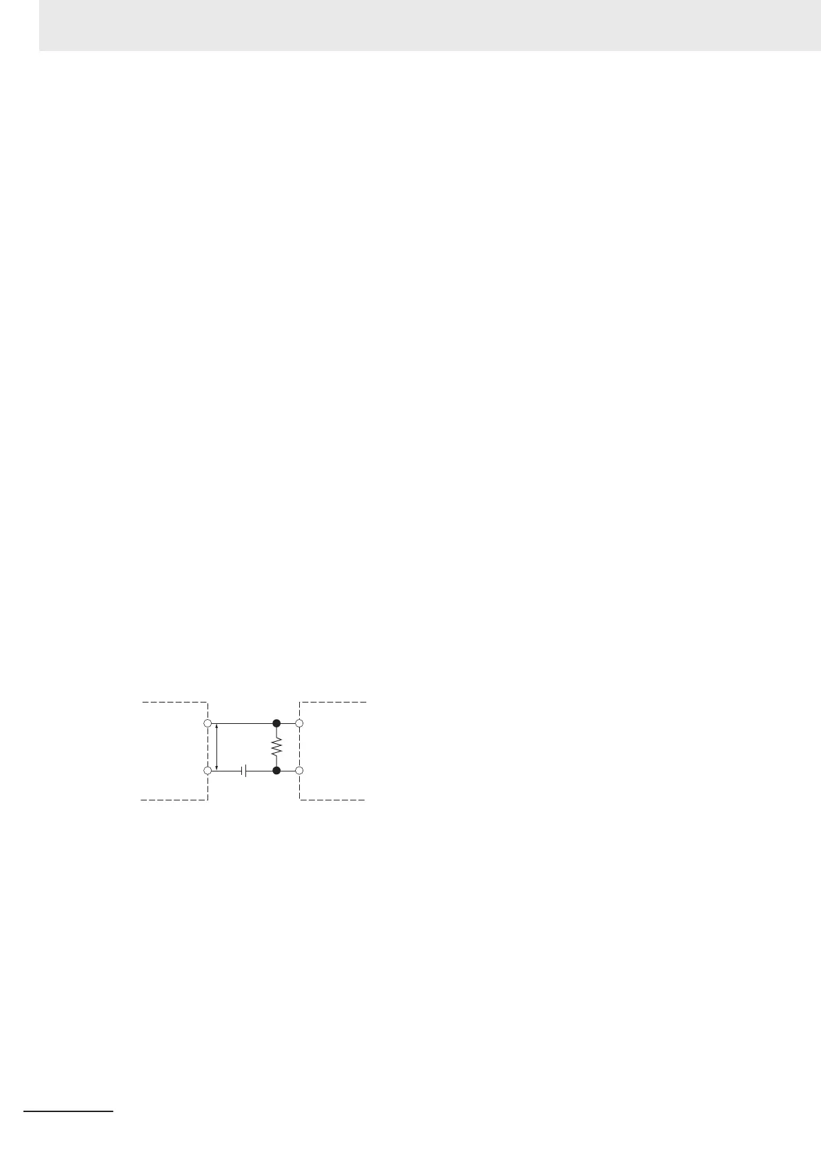
Two-wire sensor
General digital input
and flag input
V
R
V
CC
R
V
CC
: Power supply voltage V
R
: Sensor's output residual voltage
V
ON
: ON voltage of DC input I
OUT
: Sensor control output (load current)
V
OFF
: OFF voltage of DC input I
leak
: Sensor leakage current
I
ON
: ON current of DC input R: Bleeder resistor
I
OFF
: OFF current of DC input
R
IN
: Input resistor of DC input
(d) Precautions on sensor inrush current
An incorrect input may occur due to sensor inrush current if a sensor is turned ON after the DC
input section has started up to the point where inputs are possible.
5 Installation and Wiring
5-66
NX-series NX1P2 CPU Unit Hardware User’s Manual (W578)

 Loading...


