Controller
DC I/O
device
AC I/O
device
Terminal block
Example of Arrangement in Panel
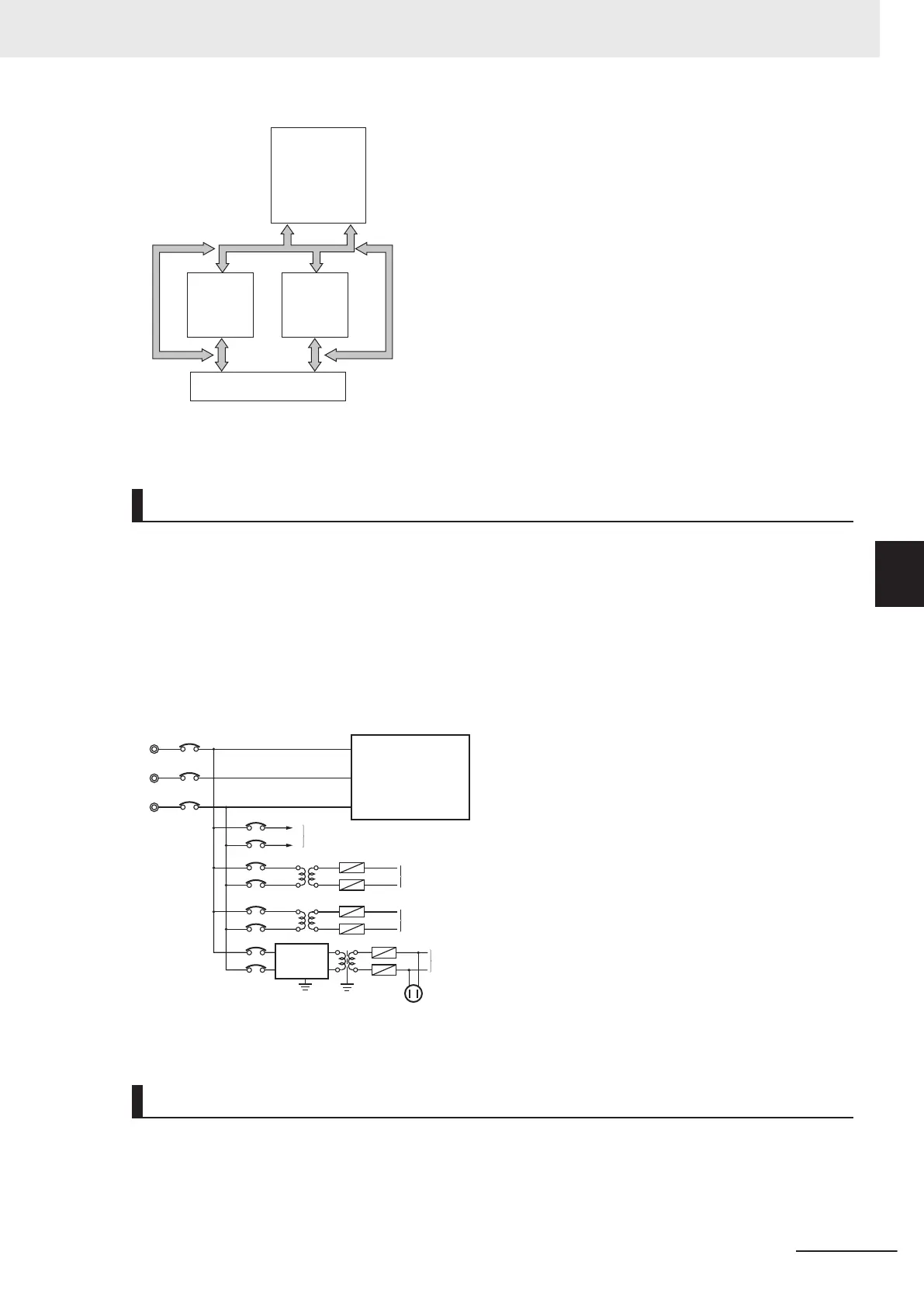
Wire Layout for the Power Supply System
Observe the following points when wiring the power supply system.
• Separate the Controller power supply from the I/O device power supply and install a noise filter near
the Controller power supply feed section.
•
Use an isolating transformer to significantly reduce noise between the Controller and the ground. In-
stall the isolating transformer between the Controller power supply and the noise filter, and do not
ground the secondary coil of the transformer.
• Keep the wiring between the transformer and the Controller as short as possible, twist the wires
well, and keep the wiring separate from high-voltage and power lines.
Unit power supply for Controller
I/O power supply for Controller
Power Supply Sy
stem Diagram
Power circuits
Power supply for general operations circuits
Outlet (for peripheral devices)
I/O power supply for Controller
Noise
filter
Wiring External I/O Signal Lines
Observe the following points when wiring external I/O signal lines.
• T
o absorb reverse electromotive force when an inductive load is connected to an output signal, con-
nect a surge suppressor near the inductive load in an AC circuit, or connect a diode near the induc-
tive load in a DC circuit.
5 Installation and Wiring
5-87
NX-series NX1P2 CPU Unit Hardware User’s Manual (W578)
5-5 Control Panel Installation
5
5-5-5 Electrical Environment
 Loading...


