87
Digital I/O Units Section 4-6
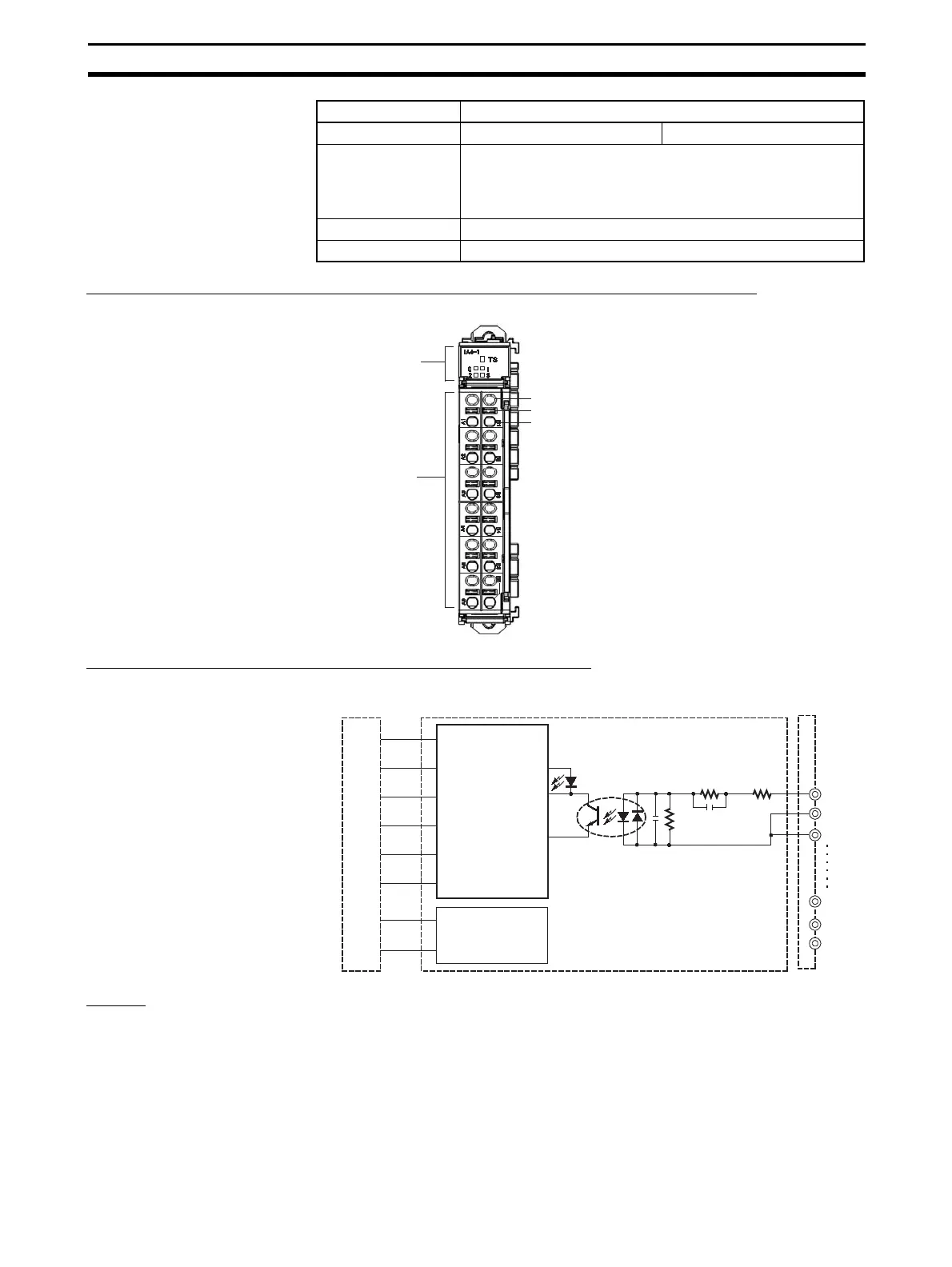
Component Names and Functions (Same for GRT1-IA4-1 and GRT1-IA4-2)
Internal Circuits (Same for GRT1-IA4-1 and GRT1-IA4-2)
Wiring Perform wiring as shown in the following figure.
OFF response time 55 ms max. 40 ms max.
Number of circuits 4 (no common)
It is necessary to share the same neutral AC signal or make
sure that the voltage between two input circuits is 600 V max.
(Refer to Wiring on page 87.)
Insulation resistance 20 MΩ min.
Dielectric strength 2,500 VAC (between AC input circuit and 24-V Unit circuit)
Item Specification
LED indicators
Indicate the Unit's status.
Terminal Block
Test pin
Release button
Terminal insertion hol
Terminal bloc
I/O LED
0A
0B
0B
3A
3B
3B
Base block
Main block
Internal circuits
Internal circuits

 Loading...


