3-51
3-4 Cable and Connector Specifications
3
Specifications
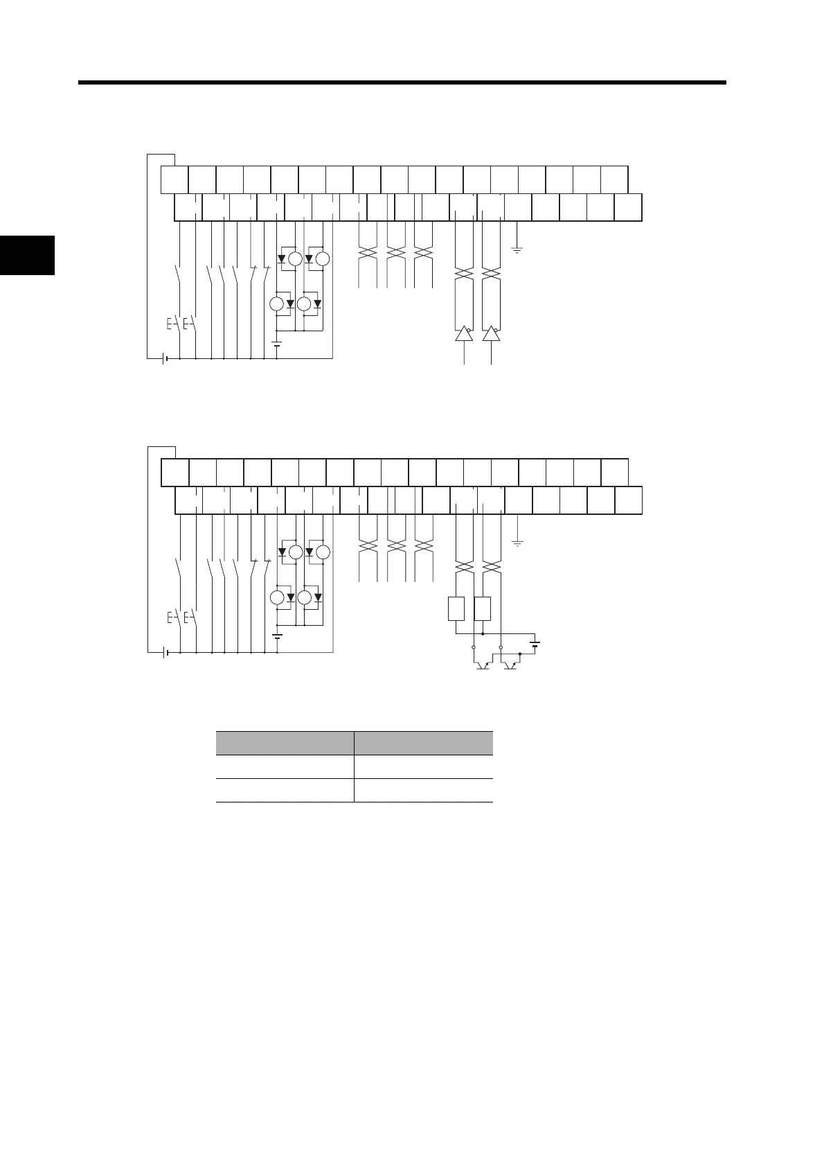
Terminal Block Wiring Example (for XW2B-34G4, XW2B-34G5, and XW2D-34G6)
Line-driver Connections
*1.The XB contacts are used to turn the electromagnetic brake ON and OFF.
Open-collector Connections
*1. The XB contacts are used to turn the electromagnetic brake ON and OFF.
*2. Select a value for resistance R so that the input current will be from 7 to 15 mA. (Refer to the
following table.)
Vcc R
24 V 2 kΩ
12 V 1 kΩ
RUN
1
2
33
34
FG
24 VDC
X1 XB
X1
ECRST
VSEL2
RESET
GESEL
VSEL1
GSEL
VZERO
TLSEL
NOT
POT
/ALM
INP
TGON
BKIR
WARN
OGND
GND
+A
−A
+B
−B
+Z
−Z
Z
+CW
+PULS
+FA
−CW
−PULS
−FA
+CCW
+SIGN
+FB
−CCW
−SIGN
−FB
X
X
+24V
(*1)
24 VDC
RUN
1
2
33
34
FG
X1 XB
ECRST
VSEL2
RESET
GESEL
VSEL1
GSEL
VZERO
TLSEL
NOT
POT
/ALM
INP
TGON
BKIR
WARN
OGND
GND
+A
−A+B
-B +Z
−Z
Z
+CW
+PULS
+FA
+CCW
+SIGN
+FB
X
X
R R
*2 *2
Vcc
24 VDC
X1
24 VDC
−CW
−PULS
−FA
−CCW
−SIGN
−FB
+24V
(*1)