2-19
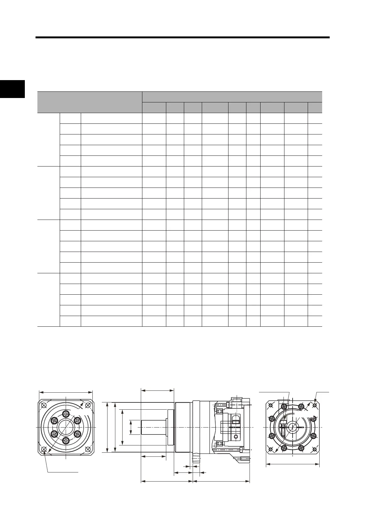
2-2 External and Mounted Dimensions
2
Standard Models and Dimensions
Decelerator Dimensions
Backlash = 3’ Max.
Decelerators for Cylindrical Servomotors
Note 1. The standard models have a straight shaft. A model with a key and tap is indicated by adding “J” to the
end of the model number (the suffix shown in the box).
Note 2. The diameter of the motor shaft insertion hole is the same as the shaft diameter of the corresponding
motors.
Outline Drawings
Model
(R88G-)
Dimensions (mm)
LM LR C1 C2 D1 D2 D3 D4 D5
50 W
1/5
HPG11B05100B@
39.5 42 40 40 × 40 46 46 40.0 39.5 29
1/9
HPG11B09050B@
39.5 42 40 40 × 40 46 46 40.0 39.5 29
1/21
HPG14A21100B@
64.0 58 60 60 × 60 70 46 56.0 55.5 40
1/33
HPG14A33050B@
64.0 58 60 60 × 60 70 46 56.0 55.5 40
1/45
HPG14A45050B@
64.0 58 60 60 × 60 70 46 56.0 55.5 40
100 W
1/5
HPG11B05100B@
39.5 42 40 40 × 40 46 46 40.0 39.5 29
1/11
HPG14A11100B@
64.0 58 60 60 × 60 70 46 56.0 55.5 40
1/21
HPG14A21100B@
64.0 58 60 60 × 60 70 46 56.0 55.5 40
1/33
HPG20A33100B@
66.5 80 90 55 dia. 105 46 85.0 84.0 59
1/45
HPG20A45100B@
66.5 80 90 55 dia. 105 46 85.0 84.0 59
200 W
1/5
HPG14A05200B@
64.0 58 60 60 × 60 70 70 56.0 55.5 40
1/11
HPG14A11200B@
64.0 58 60 60 × 60 70 70 56.0 55.5 40
1/21
HPG20A21200B@
71.0 80 90 89 dia. 105 70 85.0 84.0 59
1/33
HPG20A33200B@
71.0 80 90 89 dia. 105 70 85.0 84.0 59
1/45
HPG20A45200B@
71.0 80 90 89 dia. 105 70 85.0 84.0 59
400 W
1/5
HPG14A05400B@
64.0 58 60 60 × 60 70 70 56.0 55.5 40
1/11
HPG20A11400B@
71.0 80 90 89 dia. 105 70 85.0 84.0 59
1/21
HPG20A21400B@
71.0 80 90 89 dia. 105 70 85.0 84.0 59
1/33
HPG32A33400B@
104.0 133 120 122 dia. 135 70 115.0 114.0 84
1/45
HPG32A45400B@
104.0 133 120 122 dia. 135 70 115.0 114.0 84
C1 × C1
E
C2
Set bolt (AT)
Four, Z2
Four, Z1 dia.
D3 dia., height: 7
D4 dia.
D5 dia.
S dia., height: 7
T
F1
F2
LR
G
LM
D2 dia.
D1 dia.