3-3
3-1 Servo Drive Specifications
3
Specifications
Main Circuit and Servomotor Connector Specifications (CNA and CNB)
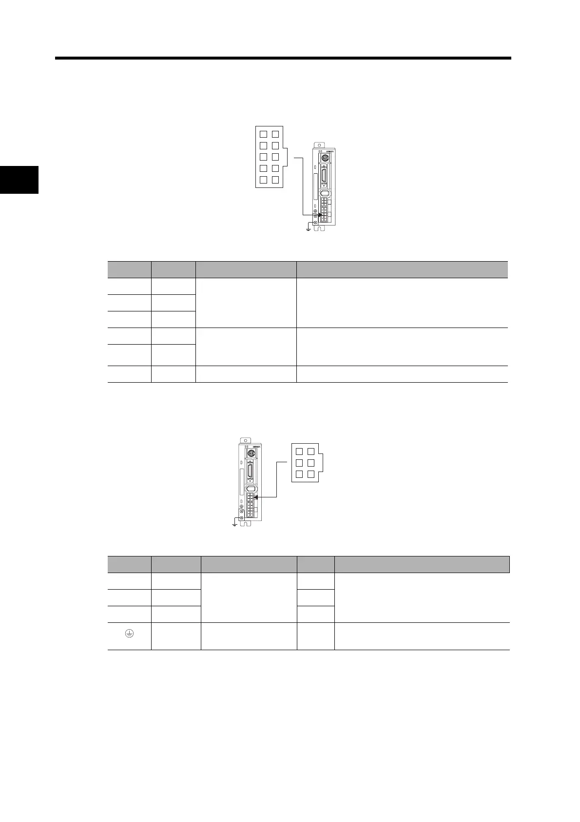
R7A-CNB01P Main Circuit Connector (CNA) Specifications
Main Circuit Connector (CNA) Pin Arrangement
R7A-CNB01A Servomotor Connector (CNB) Specifications
Servomotor Connector (CNB) Pin Arrangement
Symbol Pin No. Name Function
L1 10
Main circuit power
supply input terminals
For three-phase 200 V, connect to L1 (pin 10), L2
(pin 8), and L3 (pin 6).
For single-phase 100/200 V, connect to L1 (pin 10)
and L3 (pin 6).
L2 8
L3 6
P 5 External Regeneration
Resistor connection
terminals
If regenerative energy is high, connect an External
Regeneration Resistor.
B1 3
FG 1 Frame ground This is the ground terminal. Ground to 100 Ω or less.
Symbol Pin No. Name Color Function
U1
Servomotor
connection terminals
Red
These are the output terminals to the Ser-
vomotor. Be careful to wire them correctly.
V4 White
W6 Blue
3 Frame ground
Green/
Yellow
Connect the Servomotor FG terminals.
CNA Connector
510
16
C
N
1
C
N
2
C
N
A
C
N
B
C
N
3
PWR
ALM
CNB Connector
C
N
1
C
N
2
C
N
A
C
N
B
C
N
3
PWR
ALM
36
14