3-13
3-1 Servo Drive Specifications
3
Specifications
Control Output Details
The details of the output pins for the CN1 connector are described as follows.
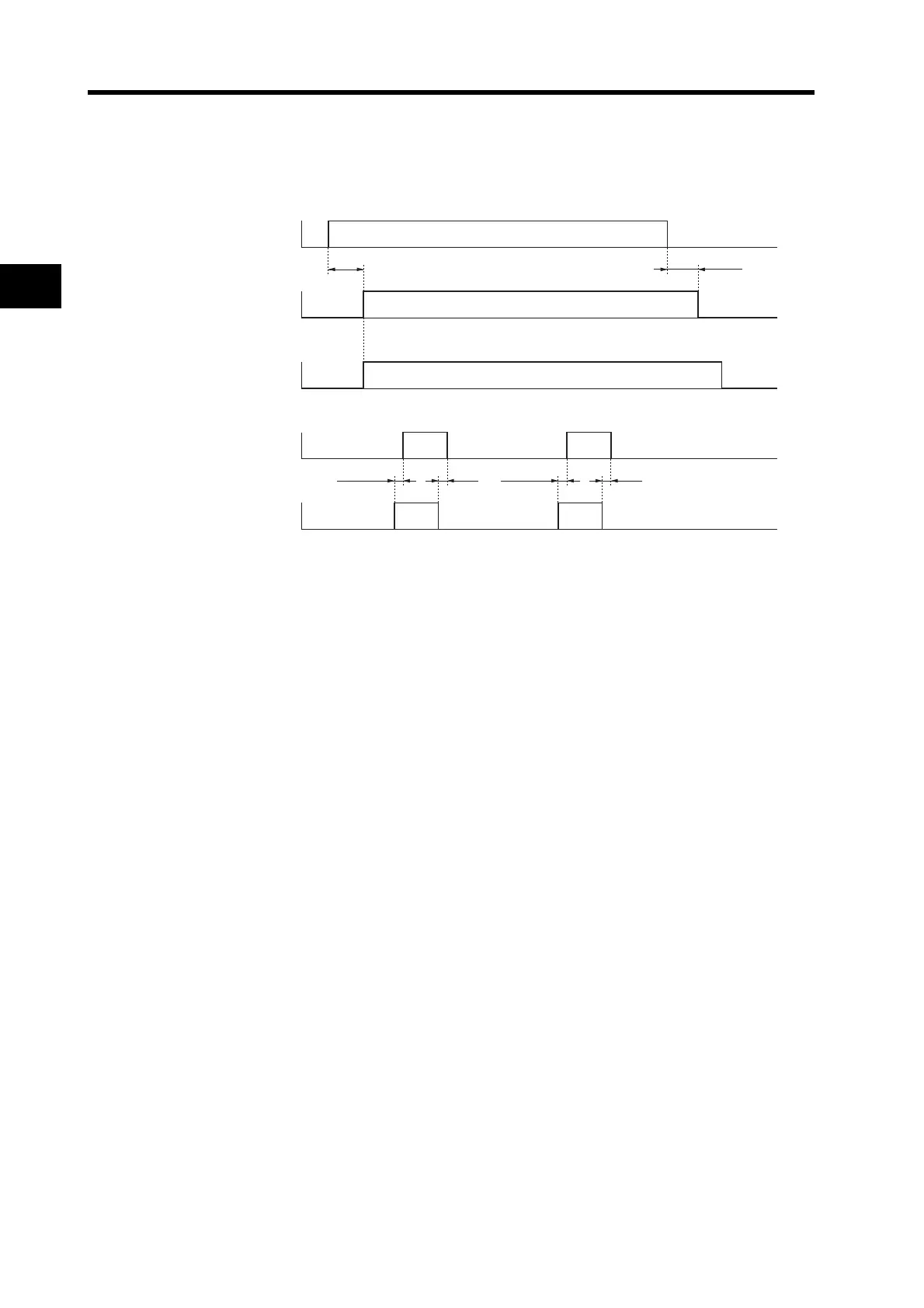
Control Output Sequence
Alarm Output
Pin 9: Alarm Output (/ALM)
Function
The alarm output is turned OFF when the Servo Drive detects an error.
This output is OFF at startup, but turns ON when the initial processing of the Servo Drive has been
completed.
Positioning Completed Output/Servomotor Rotation Speed Detection Output
Pin 10: Positioning Completed Output/Servomotor Rotation Speed Detection Output (INP/TGON)
Function: Positioning Completed Output
Pin 10 is the Positioning Completed Output (INP) in Position Control Mode (when Pn02 is set to 0
or 2).
The INP signal turns ON when the number of accumulated pulses in the deviation counter is less
than the Positioning Completion Range (Pn60).
Function: Servomotor Rotation Speed Detection Output
Pin 10 is the Servomotor Rotation Speed Detection Output (TGON) in Internal Speed Control
Mode (when Pn02 is set to 1).
The TGON signal turns ON when the motor rotation speed exceeds the Rotation Speed for
Servomotor Rotation Detection (Pn62).
Power supply input
(L1 and L2)
Alarm Output (/ALM)
Positioning Completed
Output (INP)
Brake Interlock Output
(BKIR)
RUN Command Input
(RUN)
ON
OFF
ON
OFF
ON
OFF
ON
OFF
ON
OFF
Approx. 2 s
30 s max.
0 to 35 ms 2 ms
0 to 35 ms 2 ms