3-55
3-5 Servo Relay Units and Cable Specifications
3
Specifications
Wiring
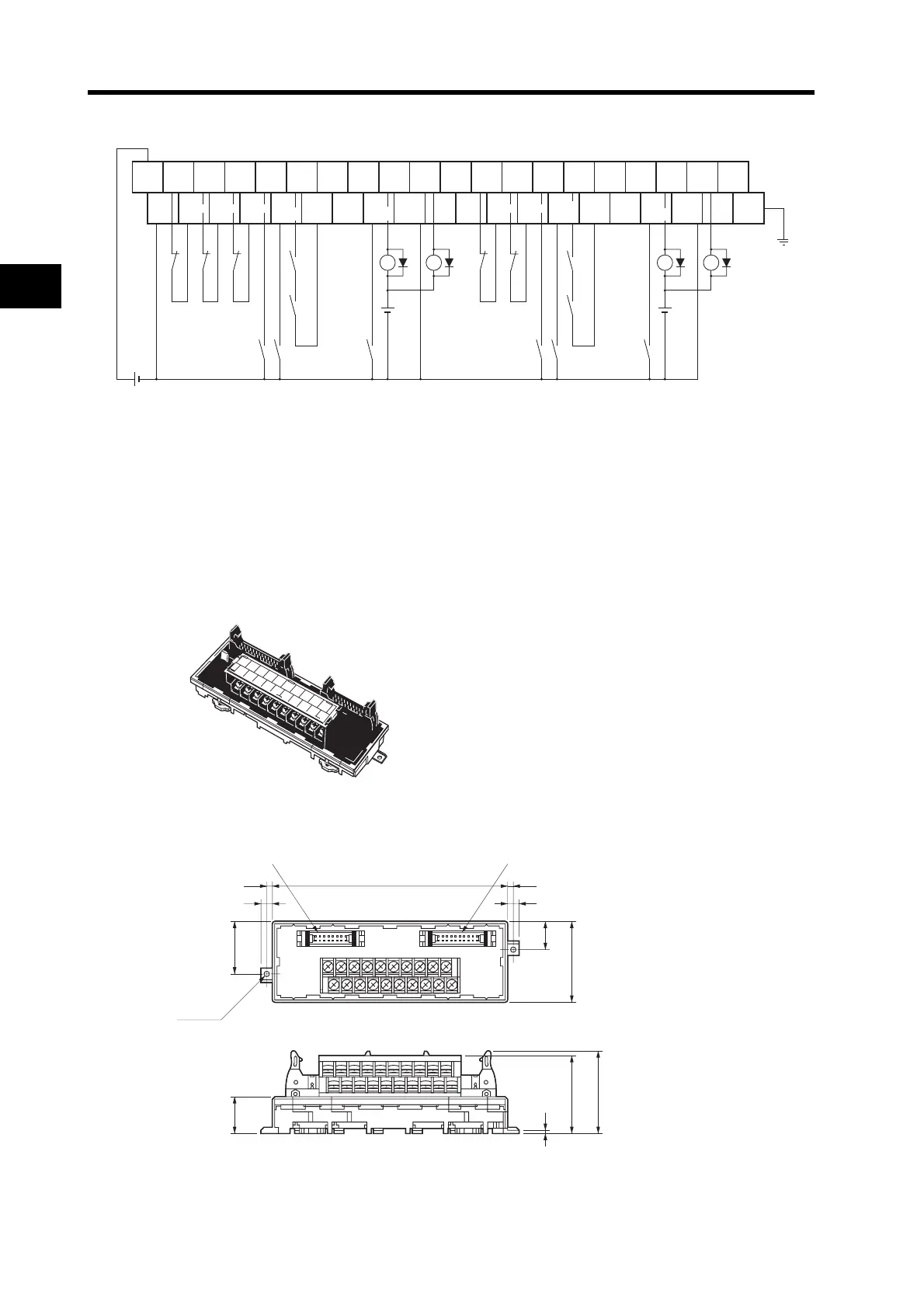
*1. The XB and YB contacts are used to turn ON/OFF the electromagnetic brake.
*2. Do not connect unused terminals.
*3. The 0 V terminal is internally connected to the common terminals.
*4. Applicable crimp terminal: R1.25-3 (round with open end).
XW2B-20J6-3B
This Servo Relay Unit connects to the following OMRON Programmable Controllers.
Dimensions
Terminal Block pitch: 7.62 mm
CQM1H-PLB21
(Pulse I/O Board for CQM1H-CPU51/CPU61)
CQM1-CPU43-V1
20
0
39
19
FG
X1 XB
24 VDC
Y1 YB
24 VDC
X1 Y1
(*1) (*1)
0 V
24 VDC
+24 V
X-axis
RUN
X-axis
ALM
X-axis
RESET
X-axis
ALMCOM
Y-axis
RESET
Y-axis
ALMCOM
X-axis
BKIR
Y-axis
ALM
Y-axis
BKIR
Common Common Common Common Common Common Common Common Common
X/Y-axis
emergency
stop
X-axis
origin
proximity
Y-axis
external
interrupt
X-axis
CW
limit
X-axis
CCW
limit
Y-axis
RUN
Y-axis
origin
proximity
Y-axis
CW
limit
Y-axis
CCW
limit
X-axis
external
interrupt
0
1
2
3
4
5
6
7
8
9
10
11
12
13
14
15
16
17
18
19
29.5
7
3.5
Two,
3.5 dia.
7
3.5135
15.5
45
20.5
44.3
2
0
10
9
19
(46)
CQM1 connector Servo Drive connector