4-36
4-4 Regenerative Energy Absorption
4
System Design
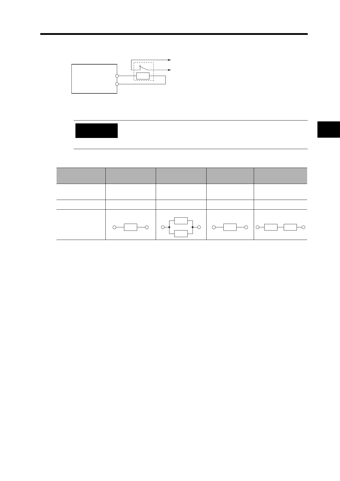
Wiring Method
Connect the External Regeneration Resistor between terminals P and B1.
Combining External Regeneration Resistors
Connect the thermal switch output so that the power supply is shut OFF
when the contacts open. Configure a sequence to shut OFF the power via
the thermal output. Not doing so may cause the resistor to overheat,
resulting in a fire or damage to the equipment.
Regeneration ab-
sorption capacity
*1
*1. Select a combination that has an absorption capacity greater than the average regeneration power (Pr).
20 W 40 W 70 W 140 W
Model
R88A-RR08050S
R88A-RR080100S
R88A-RR08050S
R88A-RR080100S
R88A-RR22047S R88A-RR22047S
Resistance
*2
*2. Do not use a combination of resistors with a resistance lower than the minimum external regenerative
resistance of each Servo Drive. For information on the minimum external regenerative resistance, refer to
Servo Drive Regenerative Energy Absorption Capacity on page 4-35.
50 Ω/100 Ω 25 Ω/50 Ω 47 Ω 94 Ω
Connection
method
P
B1
5
3
CNA
θ>
Thermal Switch Output
Servo Drive
External
Regeneration
Resistor
Precautions
for Correct Use
R
R
R
R
R R