Appendix-1
App
Appendix
Appendix
Appendix Connection Examples
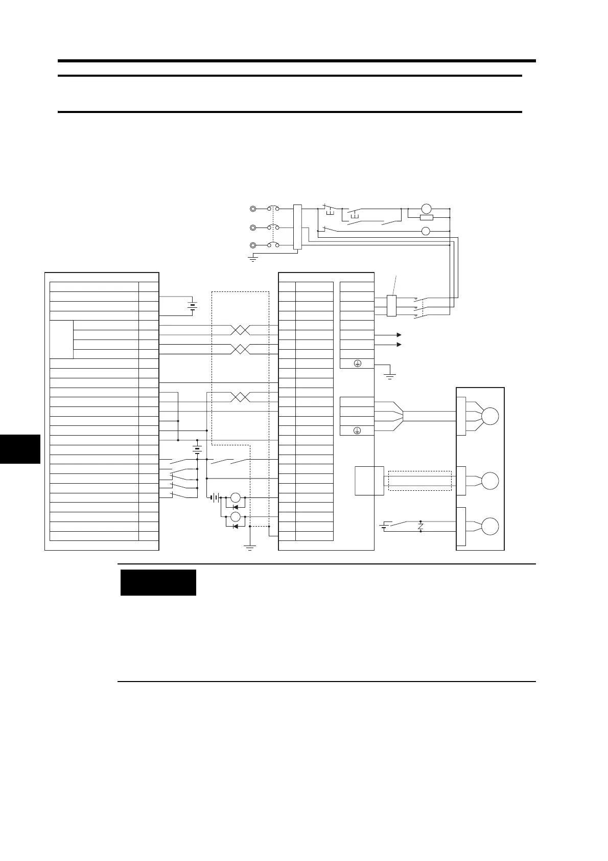
Connection Example 1: Connecting to SYSMAC CJ1W-NC133/233/433 Position
Control Units
0-V power supply for output
24-V power supply for outputs
Reactor
Servomotor Power
Cable
R7A-CAB@S
Main circuit
power supply
Main circuit contactor
Servo error display
Surge suppressor
CJ1W-NC133/233/433
R7D-BP@
R88M-G
@
Contents
5-VDC power supply (for pulse output)
5-V GND (for pulse output)
X-axis dev. cntr. reset output
X-axis origin input (24 V)
X-axis origin common
X-axis positioning complete input
X-axis input common
X-axis external interrupt input
X-axis origin proximity input
X-axis CCW limit input
X-axis CW limit input
X-axis emerg. stop input
X-axis
pulse output
Red
White
Blue
Green/
Yellow
Noise filter
3-phase 200/240 VAC 50/60 Hz
(Ground to
100 Ω or less.)
Connect External Regeneration
Resistor when required.
R7A-CPB@S
CW (output (+))
CW (output (
−))
CCW (output (+))
CCW (output (
−))
Encoder Cable
R88A-CRGB@C
Brake Cable
R88A-CAGA@B
+CW
−CW
ECRST
+24VIN
+CCW
−CCW
5 VDC
24 VDC
X1
24 VDC
24 VDC
XB
No.
CN1 CNA
A4
A3
22
23
4
14
21
10
1
2
13
9
11
L1
L2
U
V
W
GND
INP
RUN
0GND
/ALM
FG
Z
A9
A13
A12
A11
A20
A15
A17
A19
A18
A16
CN2
M
E
X1
XB
B
BKIR
A5
A6
A7
A8 25
24
A1
A2
CNB
L3
P
B1
26
R
T
MC1
NFB
ONOFF
X1
MC1
PL
S
MC1
SUP
X1
Incorrect signal wiring can cause damage to Units and the Servo Drive.
Leave unused signal lines open and do not wire them.
Use mode 2 for origin search.
Use the 5-VDC power supply for the command pulse inputs as a dedicated
power supply.
Do not share the power supply for brakes (24 VDC) with the 24-VDC power
supply for controls.
Recommended surge absorption diode: RU2 (Sanken Electric) or the
equivalent
Precautions
for Correct Use
 Loading...


