Appendix-9
App
Appendix
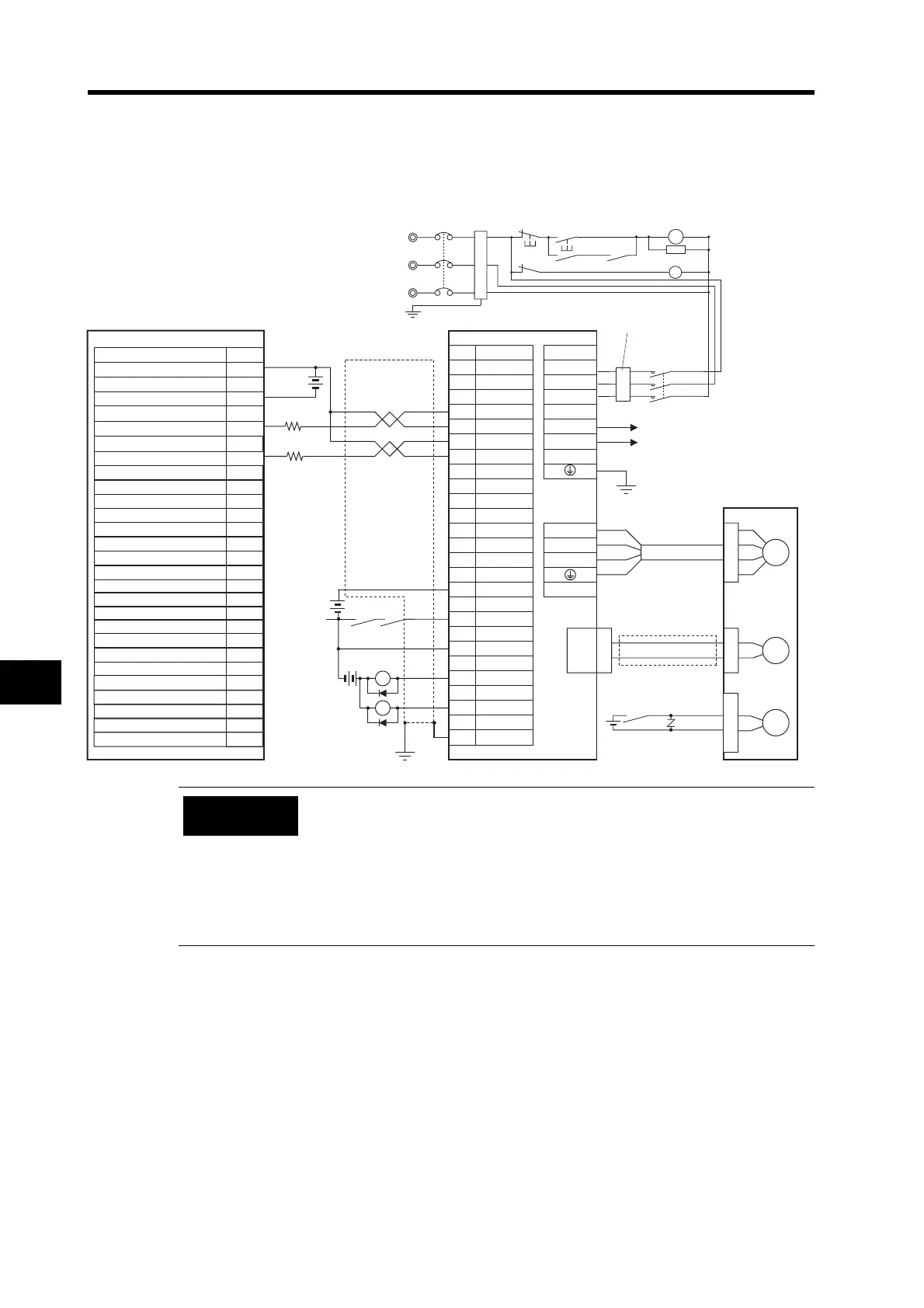
Connection Example 9: Connecting to SYSMAC CPM2C
CPU Unit with 10 inputs and outputs
An example of a transistor output (sink model).
CN1 CNA
25
22
23
4
14
21
10
1
2
13
9
11
24
L1
L2
U
V
W
GND
INP
RUN
0GND
/ALM
FG
Z
CN2
M
E
24 VDC
B
BKIR
CNB
No.
24 V
A10
A9
A1
A2
X1
XB
24 VDC
24 VDC
L3
P
B1
26
2 kΩ
2 kΩ
ECRST
COM (
−)
OUT 00 CW pulse output
OUT 01 CCW pulse output
CPM2C-10C@DTC-D
3-phase 200/240 VAC 50/60 Hz
Noise filter
R7D-BP@
R7A-CPB@S
R88M-G
@
Contents
Servomotor Power
Cable
R7A-CAB@S
+CW
−CW
+24VIN
Red
White
Blue
+CCW
−CCW
Encoder Cable
R88A-CRGB@C
Green/
Yellow
(Ground to
100 Ω or less.)
Connect External Regeneration
Resistor when required.
Reactor
Brake Cable
R88A-CAGA@B
X1
24 VDC
XB
S
R
T
NFB
ONOFF
X1
MC1
MC1
X1
SUP
PL
MC1
Main circuit
power supply
Main circuit contactor
Servo error display
Surge suppressor
Incorrect signal wiring can cause damage to Units and the Servo Drive.
Leave unused signal lines open and do not wire them.
Use the 24-VDC power supply for the command pulse inputs as a
dedicated power supply.
Do not share the power supply for brakes (24 VDC) with the 24-VDC power
supply for controls.
Recommended surge absorption diode: RU2 (Sanken Electric) or the
equivalent
Precautions
for Correct Use