3-33
3-4 Cable and Connector Specifications
3
Specifications
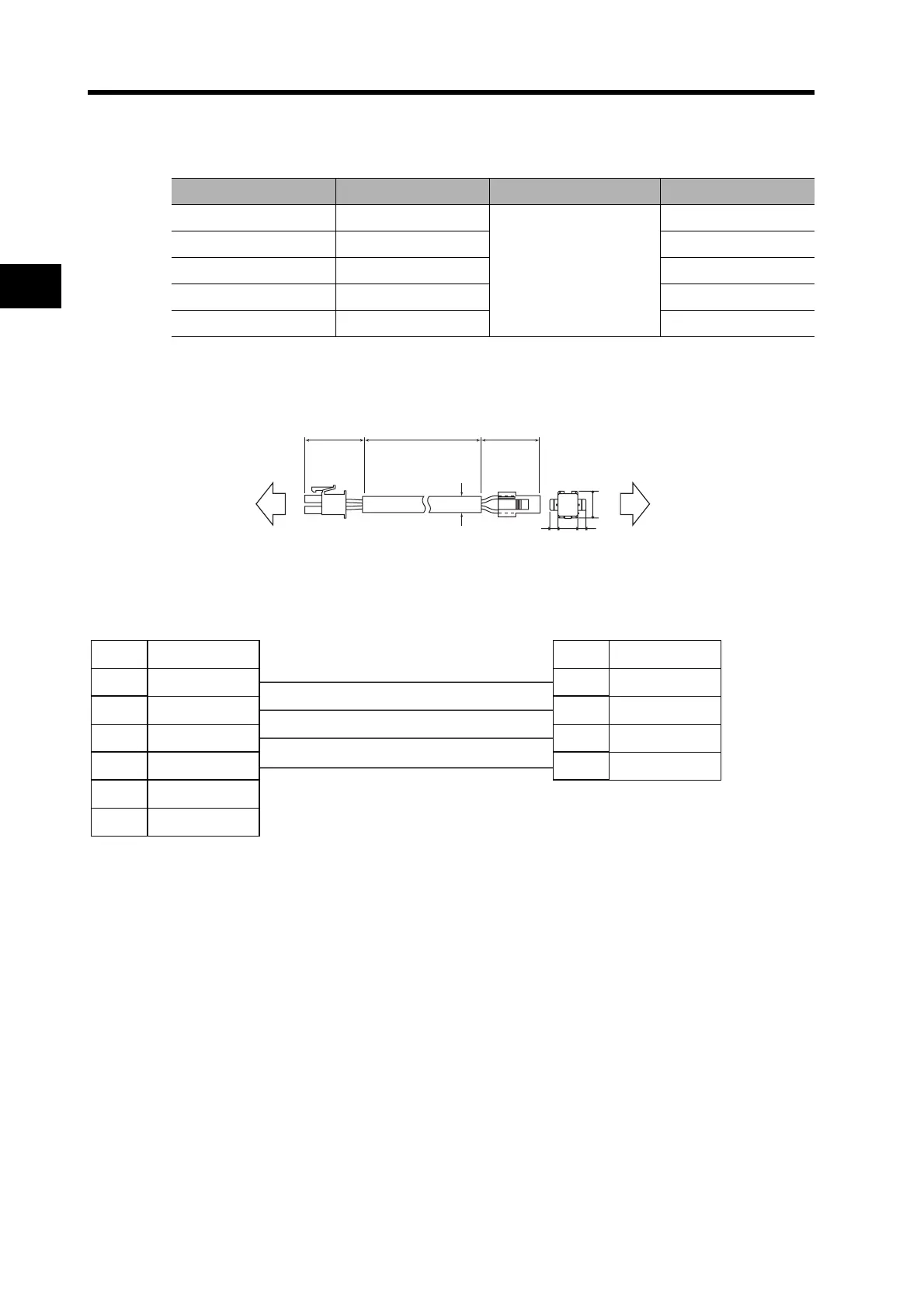
Robot Cables for Servomotor Power (with CNB Connector)
Cable Models
Connection Configuration and External Dimensions
Wiring
Model Length (L)
*1
Outer diameter of sheath Weight
R7A-CAB003SR 3 m
6.9
dia.
Approx. 0.2 kg
R7A-CAB005SR 5 m Approx. 0.3 kg
R7A-CAB010SR 10 m Approx. 0.7 kg
R7A-CAB015SR 15 m Approx. 1.0 kg
R7A-CAB020SR 20 m Approx. 1.3 kg
*1. The maximum distance between the Servo Drive and Servomotor is 20 m.
50 50L
10.0
12.0
44
6.9 dia.
Servo Drive end
Servomotor end
R88M-G@
R7D-BP@
1
No.
4
6
3
2
5
1
No.
4
3
2
FG FG
Servo Drive
Servomotor
Signal
Signal
Phase-U Phase-U
Phase-V
Phase-V
Phase-W
Phase-W
Red
White
Black
Green/Yellow
Cable: AWG20 × 4C UL2464
Servo Drive Connector
Connector pins:
5556PBTL (Molex Japan)
Connector case:
5557-06R-210 (Molex Japan)
Servomotor Connector
Connector pins:
170366-1 or 170362-1
(Tyco Electronics AMP KK)
Connector case:
172159-1 (Tyco Electronics AMP KK)