User Manual
Advanced Console Server & RIM Gateway User Manual 185
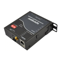
The ACM5004-2-I model is supplied with a green connector
block on the side by default. The first two connectors on this
block (marked DIO1 and DIO2) can be configured to have
external environmental sensors attached.
The industrial ACM5508-2-I and ACM5504-5-G-I models
are also supplied with a green connector block on the
side by default. The first two connectors on this block
(marked DIO1 and DIO2) can be configured to have
external environmental sensors attached.
Note: The ACM5000-E Sensor ‘inputs’ are four ‘dry contact’ inputs which are normally open (NO). When open these are
sensed as a TTL high or digital ‘1’. When activated the external devices (door close, vibration, water, smoke)
present a short circuit and the contact ‘closes to ground’ which is read as a TTL low or a digital ‘0’.
For custom applications a user can sense the state (closed or open) of non-Opengear dry contact sensors
through the UI or command line.
It is also possible to control the sensor pins as ‘outputs’. The user can set the pins as TTL high (1) or low (0) as
required for their low voltage/low current application.
The ACM5004-2-I, ACM5508-2-I and ACM5504-5-G-I models have specific dedicated I/O (DIO1 & DIO2) and
output only pins (OUT1 & OUT2), the later having inverting outputs with higher voltage/current transistor
By default on the ACM5000 and ACM500 each SENSOR and DIO port is configured as an Input, so they are available to
be used with external environmental sensors attached
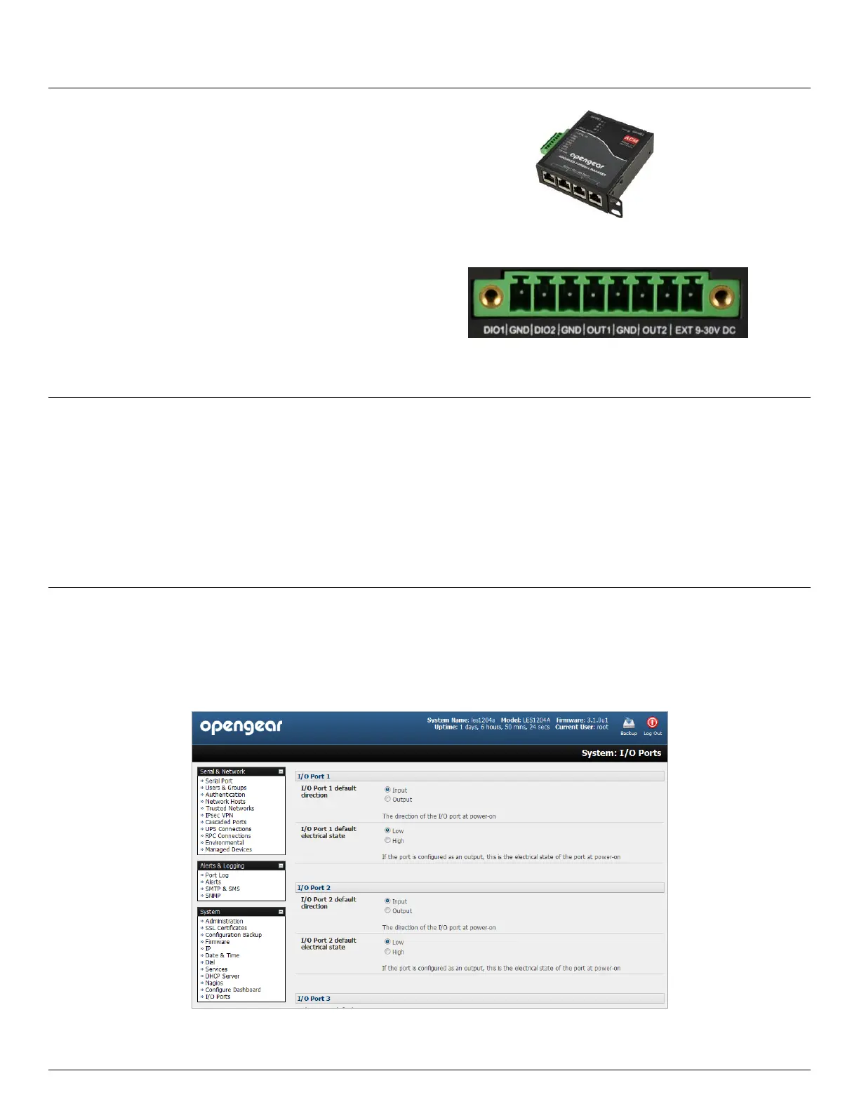
To confirm the direction and state configurations for these ports you can select the System: I/O Ports menu and
a table with the summary status of the four digital I/O ports will be displayed. I/O Port1 = DIO1 or SENSOR1, I/O
Port2 = DIO2 or SENSOR2, I/O Port3 = SENSOR3 and I/O Port4 = SENSOR 4)