OPI-3601
Specifications Manual
6
5. Electrical Specifications
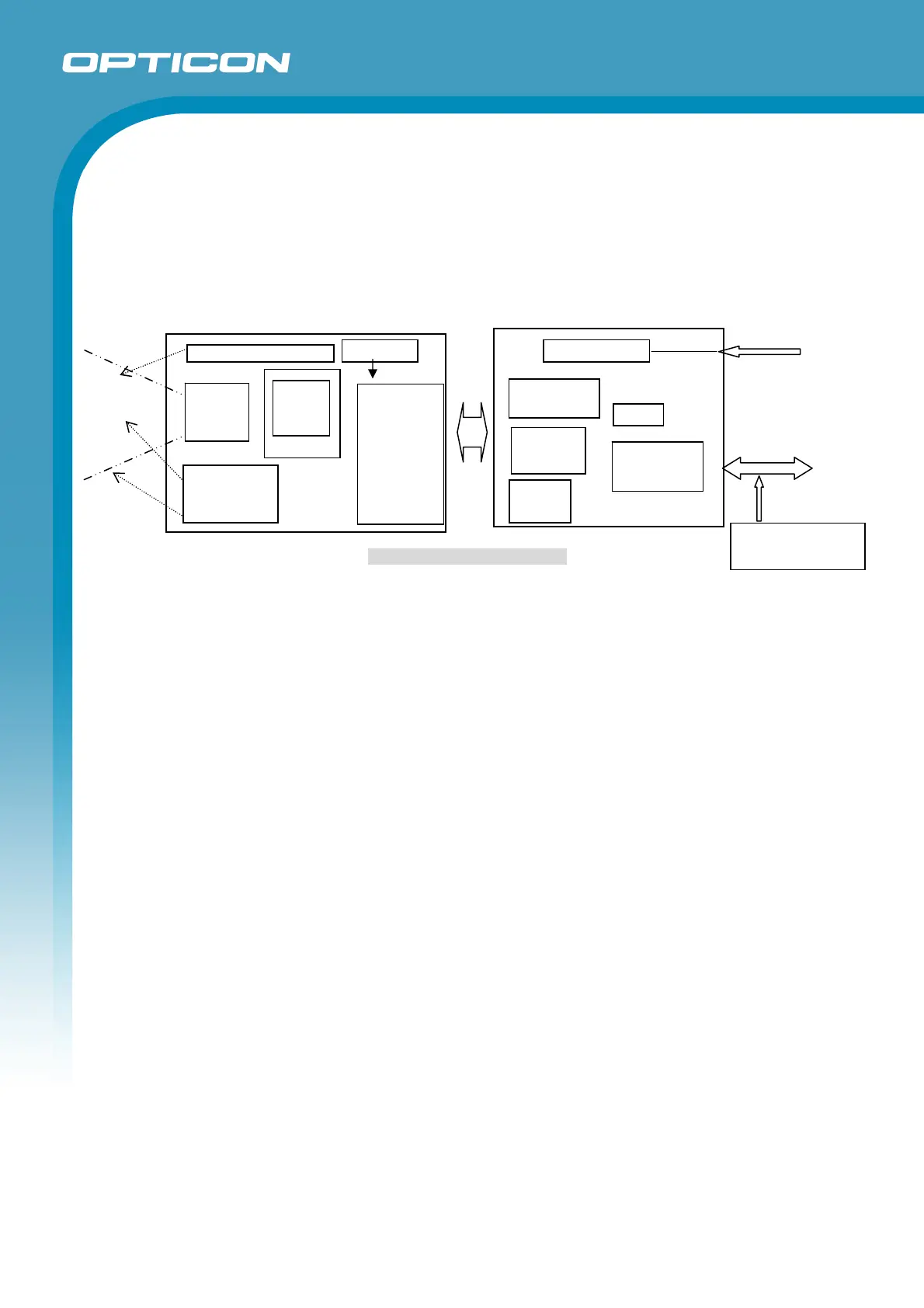
The OPI-3601 comprises ‘Camera Module Section’ with CMOS sensor, ‘Decoder Section’ for decoding
1D / 2D code data from a scanned image, ‘Communication Control Section’ to communicate with a host
and ‘Power Supply Section’ for the main power supply conversion.
The USB model is bus powered and no adapter is needed. The RS-232C and Wedge PS/2 models
need a dedicated adapter for DC 6.0 V power. Make sure not to insert and remove the power adapter
when PC is on. It may cause the PC to malfunction.
Figure 2: Configuration Diagram
5.1. AC Adapter Specifications
For RS-232C and Wedge PS/2 models
5.1.1. Input Specifications
Power supply voltage : AC 90 ~ 265 V
Power supply frequency : 47 ~ 63 Hz
Maximum current : 0.5 A (max)
5.1.2. Output Specifications
Output voltage : 6.0 V ±5% / Output current: 0 ~ 2.0 A (max)
Power ripple : 100 mVp-p (max, rated load)
5.2. Wedge PS/2 Power Supply (Host)
Input power supply voltage : DC 5.0 V
Range of working voltage : 4.5 ~ 5.5 V
Power ripple : 100 mVp-p max (10 ~ 100 kHz, power supply voltage 5.0 V)
Current consumption : 100 mA (max) without main power supply (AC adapter)
* Current consumption from the main power supply in standby state: 75 mA (max)
* Current consumption from the main power supply during reading operation: 300 mA (max)
* Keyboard operation is possible when the main power supply is off.
* The current consumption was measured at 25°C.
5.3. USB Power Supply
Bus-Power Class : Hi-Power (500 mA max)
Current consumption : 75 mA (max) in stand-by mode
: 300 mA (max) during reading operation
* The current consumption was measured at 25°C.
Power Supply Section
Camera Module & Decoder Section
CMOS sensor
Host
CPU +
FROM/SDRAM
3.3VÅ+5.0~6.0V
I/F
(RS-232C/USB
/Wedge)
Buzzer
+6.0/5.0V
AC adapter
/Host
Status LED
Illumination
Red LED (2)
Keyboard
(Wedge)
Imaging
Lens
1.3VÅ3.3V
Trigger
button
Magnet
sensor
Interface Section
Aimin
Green LED (1)
Communication Control Section