IG-150-EN version 04; 03/10/16
100
Protection functions. Description and settings General instructions
ekor.rps
4.22.3. MHO area settings range
Setting Min Max Step Notes
Z1A impedance setting (oset) [Ω]
-20.0 20.0 0.1
Z1B impedance setting (diameter) [Ω]
0.0 120.0 0.1
Area 1 undervoltage monitoring
YES/NO
Area 1 alarm time setting [s]
0.0 10.0 0.1
Area 1 tripping time setting [s]
0.00 10.00 0.01
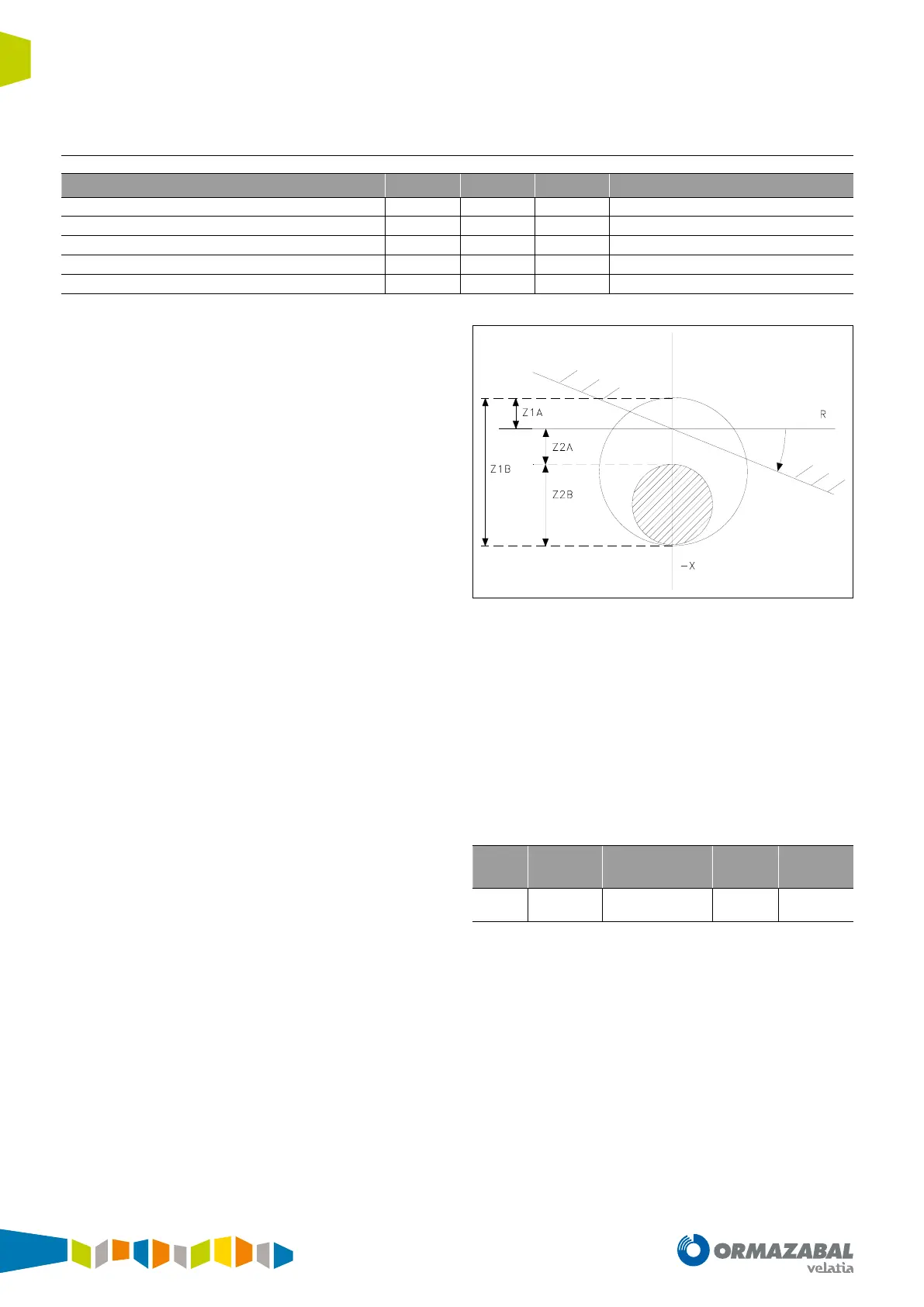
Table 4.29. MHO area settings range
The MHO2 area has the same settings range as the MHO1.
Settings Z1A and Z1B delimit the MHO1 tripping area
(settings Z2A and Z2B delimit the MHO2 area). Setting Z1A
represents the oset (in ohms) of the area’s top. This value
can be positive (see Z1A in gure 1) or negative (see Z2A for
the MHO2 area). Setting Z1B represents the diameter of the
MHO1 area.
The protection operates dierently, depending on whether
the area is in undervoltage conditions or not. For one area
to be in undervoltage conditions, one of the following
circumstances must be met:
1. That the measurement in any of the voltage phases is
below the undervoltage start value.
2. That the area’s undervoltage monitoring setting is
disabled.
When the generator enters one of the MHO areas a timer
is activated. If the area is not in undervoltage conditions
the area’s alarm timer is activated. However, if the area is
in undervoltage conditions, the tripping activates the
area’s timer. The latest timer must be set to a value below
the other timer’s. The reason for this is that in undervoltage
conditions the fault must be cleared quickly in order to
avoid the electrical system becoming unstable, since the
generator has few possibilities to recover. Once the timer’s
time has elapsed, the corresponding outputs are activated.
Angle
Figure 4.37. MHO area settings
Field loss signals:
1. MHO1 alarm
2. MHO2 alarm
3. MHO1 alarm
4. MHO2 alarm
5. MHO1 undervoltage
6. MHO2 undervoltage
The transmitted measurement is as follows:
Byte
Nr.
Format Specication Data
2
Word PROCOME V
r
*1.2*20
Impedance
module
Table 4.30. transmitted measurement
It is the voltage (1.2*V
r
) dividided by the minimum current.
To make calculations for the impedances, the positive
sequence current must be equal or higher than a minimum
value set to 0.05 A. This way, the maximum impedance
corresponds to the quotient between the maximum voltage
and the minimum current.