IG-150-EN version 04; 03/10/16
64
Protection functions. Description and settings General instructions
ekor.rps
Memory
It is polarized by the positive sequence voltage while it is
higher than a threshold. If the voltage is lower than this
value, it is polarized by means of the voltage memorized
2cycles before the voltage disappears. This memorization
is maintained 0.5 s.
Trip permission without V
pol
(Directional Locking on the
display)
This setting is used when the polarization voltage (V
1
) falls
below a threshold (setting), so that if it is set as “YES”, it
indicates forwards and if it is set as “NO”, it indicates reverse.
The memory treatment has been previously done.
Signalling
It provides forward and reverse signaling. If the direction
is forwards, the signals “Forward A”, “Forward B” and
“Forward C” get activated. If the direction is reverse, the
signals “Reverse A”, “Reverse B” and “Reverse C” get activated.
Being the trip permission without V
pol
(Directional Locking)
set as “NO”, if the polarization magnitudes are below the
threshold, the direction is not signaled.
Being the trip permission without V
pol
(Directional Locking)
set as “YES”, if the polarization magnitudes are below the
threshold, it signals reverse and forward.
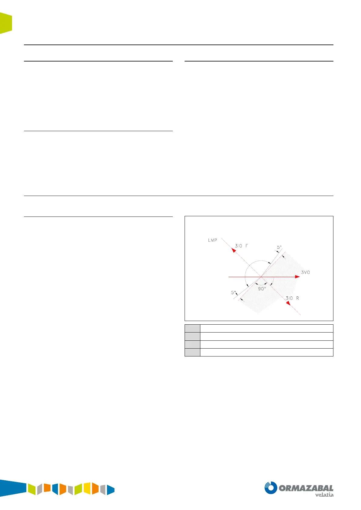
4.6.3. Neutral directional (67N); polarization by S
0
(V
0
)
Operation with polarization by V
0
, zero sequence voltage
The direction is determined using the neutral current (3 I
0
)
with the neutral voltage as polarization, (3 V
0
). The angle
determines the range in which the fault is considered
forwards and reverse. The fault is considered forwards if:
There is a 5
th
zone between the locking zone and the trip
zone, for which the present directional status is maintained.
The measurement of 3 V
0
can be obtained through a
transformer or calculated using the phase simple voltages.
If the “type of voltage” setting is set as “compound” the
calculated zero sequence voltage will always be zero. The
measurement of 3 I
0
can also be calculated as the sum of the
phase currents, in models in which there isn’t a transformer
assigned for that measurement
.
1
3
4
2
90-setting angle < arg (I
0
) – arg (V
0
) < 270-setting angle
1
Tripping zone
2
Locking zone
3
Angle covered by the tripping zone
4
Setting angle
Figure 4.7. Homopole sequence directional