IG-150-EN version 04; 03/10/16
48
Unit configuration General instructions
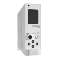
ekor.rps
The following setting is only available via the keypad/
display in IRIG-B format (at the same level as PROG.TABLE 0):
“IRIG-B format”: determines if the year in the IRIG
synchronization is taken into account or not. The options
are: “B002” (which does note take the year into account) and
“B002 IEEE 1344” (which takes the year into account).
“Analog output”: the equipment has two analog outputs,
which provide one output in milliamperes proportional to
the measured value; they can be programmed (only with a
console) as follows:
1. I
maximum
, secondary current maximeter. Full scale 6 A.
2. V
a
, V
b
, V
ac
, U average compound U, secondary compound
voltages. Full scale √3*V
r
*1.2.
3. I
n
, I
a
, I
b
, I
c
, I
average
, secondary currents. Full scale 6 A.
4. [P (active power)], secondary absolute value P. Full scale
3*V
r
*1.2*6.
5. [Q (reactive power)], secondary absolute value Q. Full
scale 3*V
r
*1.2*6.
6. [S (apparent power)], secondary absolute value S. Full
scale 3*V
r
*1.2*6.
7. [Cos A], phase A power factor absolute value. Full scale 1.
8. [Cos B], phase B power factor absolute value. Full scale 1.
9. [Cos C], phase C power factor absolute value. Full scale 1.
10. [Average cos], average power factor absolute value. Full
scale1.
11. Fault distance, given in the feeder’s total length
percentage.
The operation of the analog output used for the fault
distance is explained in the “presentation of results” section
in the “fault locator” chapter.
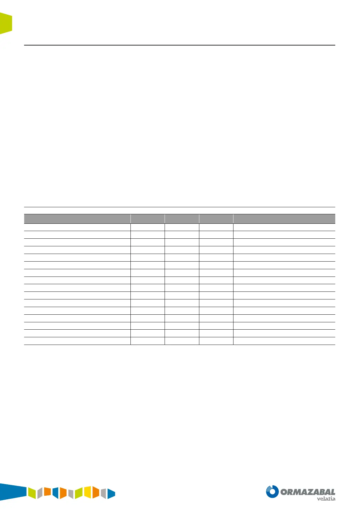
3.4.2. Setting ranges (table 0, single)
Setting Min Max Step Notes
Relay in service
YES/NO
Breaker number
5 alphanumeric char.
Events mask
See “Events”
Phase curr. turn. ratio
1 3,000 1
Neutral cur. turn. ratio
1 3,000 1
Sens. N. cur. turn ratio
1 3,000 1
Voltage turn. ratio
1 9,999 1
Simple rated voltage [V]
40.0 200.0 0.1
Type of voltage
Simple/compound
Measurement of voltage
Phases in which it is measured
IRIG-B format
B002 (without year)/B002 IEEE 1344 (with year)
Analog output 1
See “Analog output”
Analog output 2
See “Analog output”
Active energy [kWh]
1 9,999 1
Reactive energy [kVARh]
1 9,999 1
Power correction factor
0.010 2,000 0.001
Table 3.4. Setting ranges