IG-150-EN version 04; 03/10/16
99
General instructions
ekor.rps
Protection functions. Description and settings
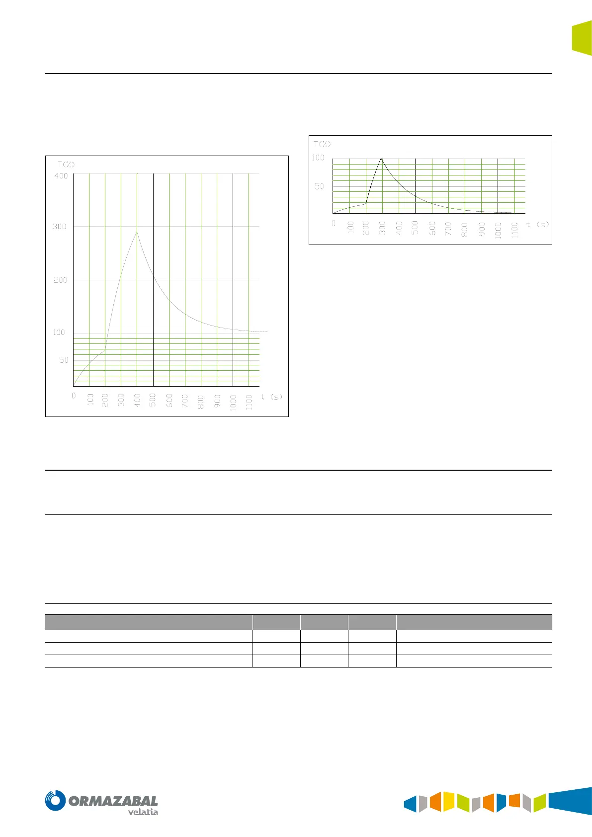
Combined examples cooling and heating:
1. Let’s suppose that during 200 s it is heated with I/I
0
=
1, the next 200 s (without tripping) with I/I
0
= 2, and
starting from there it goes back indenitely to I/I
0
= 1
(both time constants of 3 min):
Figure 4.35. Combined examples cooling and heating
2. Lets suppose that during 200 s it is heated with I/I
0
= 0.5,
then with I/I
0
= 1.5 until reaching 100 %, where it trips,
and starting from there it is cooled with I/I
0
= 0 (both
time constants of 3min).
Figure 4.36. Combined examples cooling and heating
4.22. Field loss protection
4.22.1. Overview
Field loss protection (generator excitation), with the following
characteristics (function 40):
1. 2 MHO tripping areas with independent settings.
2. 1 directional unit common to both areas.
3. 1 undervoltage unit common to both areas. Each area
can be enabled independently.
4.22.2. General settings range
Setting Min Max Step Notes
Enable
YES/NO
Minimum voltage pickup
10.0 65.0 0.1
Directional unit angle
0 180 1 Clockwise
Table 4.28. General settings range
The directional unit angle allows to block the protection in
a specic direction.
The protection’s impedance value is calculated with the
positive sequence current and voltage.