IG-150-EN version 04; 03/10/16
124
data acquisition functions General instructions
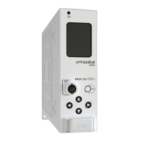
ekor.rps
3. Overvoltage protection:
a. Timed unit pickup phase A
b. Timed unit pickup phaseB
c. Timed unit pickup phase C
d. Instantaneous unit pickup phase A
e. Instantaneous unit pickup phase B
f. Instantaneous unit pickup phase C
g. Activation of output of timed unit phase A (trip)
h. Activation of output of timed unit phase B
i. Activation of output of timed unit phase C
j. Activation of output of instantaneous unit phase A
k. Activation of output of instantaneous unit phase B
l. Activation of output of instantaneous unit phase C
4. Undervoltage protection:
a. Timed unit pickup phase A
b. Timed unit pickup phase B
c. Timed unit pickup phase C
d. Instantaneous unit pickup phase A
e. Instantaneous unit pickup phase B
f. Instantaneous unit pickup phase C
g. Activation of output of timed unit phase A (trip)
h. Activation of output of timed unit phase B
i. Activation of output of timed unit phase C
j. Activation of output of instantaneous unit phase A
k. Activation of output of instantaneous unit phase B
l. Activation of output of instantaneous unit phase C
5. Inputs
a. Activation of digital input xx (1 to 17)
b. Deactivation of digital input xx (1 to 17)
6. Recloser
a. External locking of the recloser
b. External unlocking of the recloser
c. No reference voltage
d. Reclosing order
e. Definitive trip
f. Recloser in idle
g. Recloser in ongoing cycle
7. Command
a. Excessive number of trips
b. Breaker closing
c. Breaker opening
d. Breaker close command (control message or input)
e. Breaker open command (control message or input)
f. Close command failure
g. Open command failure
7. Self-checking
a. Critical Hardware error
- Converter reference voltage error
- Converter error
- FLASH memory recording error
- Relays activation error
- SPI communication error (between micro and DSP)
b. Non critical Hardware error
- Clock synchronization error
c. Hardware error corrected
7.2. fault records
The protection stores in non volatile memory a queue of
the 20 last faults retrievable from the PC with the following
information.
1. Available units
2. Units tripped during fault
3. Units picked up during fault
4. Fault starting date and time (rst picked up unit)
5. Tripping date and time (rst picked up unit)
6. Fault ending date and time (when the trip signal
disappears)
7. Current cleared by circuit breaker (maximum of phase
currents detected between the moment of the tripping
order and the breaker opening)
8. Settings group active during the fault
9. Frequency
10. Fault distance
11. Pre-fault active and reactive power
12. Fault active and reactive power
13. Reclosing number where the fault has occured
14. Type of fault and type of trip: 3 letters code made by
the characters combinations A, B, C, N y D, depending
on tripping by phase, neutral or unbalance-broken
conductor. Example: ACN is a two phase to earth fault
between phases A and C and earth
15. Pre-fault phase A current (module and angle)
16. Pre-fault phase B current
17. Pre-fault phase C current
18. Pre-fault neutral current
The pre-fault currents and voltages are simultaneous, and
they are those existing 3 cycles before the pick-up.
1. Phase A fault current (module and angle)
2. Phase B fault current
3. Phase C fault current
4. Neutral fault current