IG-150-EN version 04; 03/10/16
136
Other functions General instructions
ekor.rps
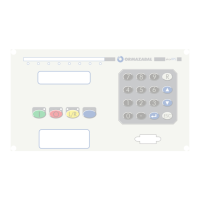
8.4. Commands by keyboard and front push-buttons
If by keyboard/display in “pushbuttons”-“enab.
pushbuttons”, “functionals” has been programmed;
commands can be executed from the keyboards and from
the pushbuttons of the unit front part.
Programming which command is executed with each key/
push-button is carried out through the console, in the
screen “commands conguration”.
In the rst row, there appear all the keys that can be used;
with ON and OFF indications, as they work as a two-state,
and when changing the state, the programmed command
is executed.
The pushbuttons execute the programmed when pushing
them (the dierence with the command “open”, “closer”, etc.
lays in the fact that “
” has to be pushed at the same time
in order to execute them). The keys execute the commands
when pushing them at the same time as key “
↑
” .
Push-button type row (conrmation) can be programmed
at “NO”, so the command is immediately executed, or at
“YES”, so conrmation is requested via display which is
validate by pushing “Intro”; if conrmation is not wished,
push “ESC”.
Several commands can be programmed for a single key,
and they are sequentially executed (up downwards).
If it has been programmed as “functionals” each key that is
pushed, is considered a control signal.
These push-buttons are only active in local mode, except
for the “L/R” push-button. When this push-button is in
remote mode and the ”local mode” or “remote mode” orders
are programmed ON or OFF, the unit switches into local.
Therefore, the other function push-buttons are active.
8.5. Power supply supervision
It is only available in those models with this option. This
function detects the voltage drop of the power supply under
the level that guarantees the correct displaying of the digital
input states. This function is enabled by setting (conguration
settings), but the limits for the detection are xed according
to the selection of the power supply (see model coding):
Power supply Detection level
125/220V
dc
84V
24/48V
dc
17V
The agony signal is activated when the power supply is
below the detection level corresponding to the supply
type. In such a situation the protection:
1. Is set out of service
2. Generates hardware error and low supply signals
3. Marks as invalid the logic signals and digital inputs
8.6. External supply supervision
It is only available in those models with the option “battery
voltage measurement”
This function checks that the external power supply voltage
is within the set margin. It generates two signals:
1. Power supply higher than the maximum threshold. If
the supply voltage exceeds the set maximum threshold
2. Power supply lower than the minimum threshold. If
the supply voltage is lower than the set maximum
threshold
The settings for this function son:
Setting Min Max Step Remarks
Enable
YES/NO
Minimum threshold [V]
20 220 1
Maximum threshold [V]
24 280 1
Table 8.4. Setting