IG-150-EN version 04; 03/10/16
87
General instructions
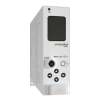
ekor.rps
Protection functions. Description and settings
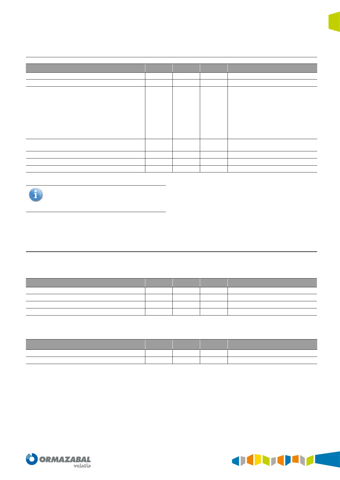
4.17.1. Setting range (6 tables)
Setting Min Max Step Notes
Enable
YES/NO (see note)
Pick up [V]
2 200 0.1
Curve type
Denite time
Normal inverse curve
Short inverse time
Long inverse time
Very inverse curve
Extremely inverse curve
Very inverse special curve
Moderately inverse curve
User curve
Time index
0.05
0.5
1.09
30.0
0.01
0.1
For IEC curves
For ANSI curves
Denite time [s]
0 600.0 0.01
Instantaneous pickup [V]
2 200 0.1
Additional time [s]
0 60.00 0.01
Table 4.22. Setting range
These settings can be found in the console
on the screen “voltage protection” in the
column “OVERVOLTAGE 3 x V
0
.”
The time delay curves are the same as the ones used by the
overcurrent protection units.
The starting voltage is set to secondary volts.
On denite time, the relay trips when the programmed
time expires since the starting voltage is exceeded,
independently of the voltage value.
4.18. Frequency protection
This function has 5 steps, programmable as minimum
frequency or maximum frequency.
The settings per step, independent for each step, are as
follows (6 tables):
Setting Min Max Step Notes
Minimum frequency enable
YES/NO
Pickup [Hz]
40 70 0.01
Denite time [s]
0 600.00 0.01
Type
Table 4.23. independent settings
The common settings for all steps are:
Setting Min Max Step Notes
Minimum supervision voltage [V]
12 200 1
Nº of pickup cycles
3 15 1
Table 4.24. Common settings
The time delay of this unit corresponds to the start set cycle
number, more than 35 ms.
In a console, the settings are in the “frequency protection”
screen. The common ones are in “frequency monitoring”.