IG-150-EN version 04; 03/10/16
122
Other settings General instructions
ekor.rps
The pulse time (duration) is the time during which the logic
signal remains active. Its programming allows two options:
1. "By logic": After the delay, the output is active as long
as there is a 1 at the programmed logic output.
2. "By time": The time during which the output is active
is programmed, so that once expired the output is
deactivated, independently from the state of the
programmed logic output. Only a new step from 0 to 1
activates the output again, after the delay.
The time range goes from 0.1 s to 599.9 s, with steps of 0.1 s.
A logic output "i" can be used as available signal for
programming input of other logic signal "j" or of itself.
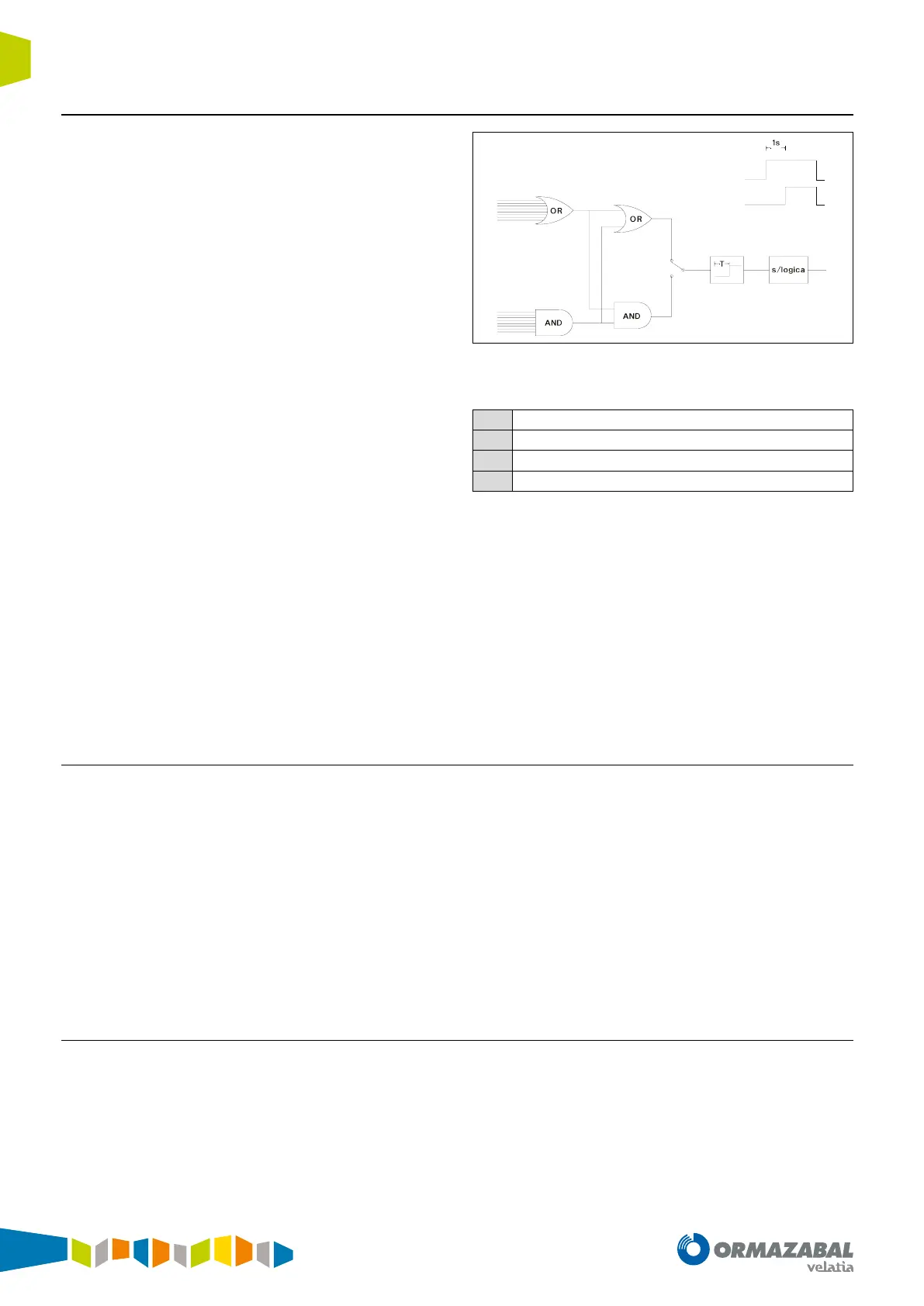
A very simple application sample: It is wished that the digital
output DO7 follows to the digital input DI6, with a delay of 1 s.
Another example of logical applications (fuse blow up
function): There are in a table (table 1) a curve that trips in
quick time, and another one (table 2) that trips in a longer
time. Logic 7 will be programmed: 79 I-T. 2
nd
reclosing security.
, T delay = 0.0 s and duration = 0.5 s. Then in “command
conguration” screen LOG 7 will be programmed, which
activates “table 2 activation”. So, after 2
nd
reclosing the active
table, in which the trip is slower, is changed. In order to go back
to the initial situation (table 1) logic 8 will be programmed:
(79 I - recl. On standby) OR (79 I - intens. denitive trip ) OR (79
I-. Intens. recloser locked) T delay = 0.0 s and duration = 0.5
s Then, in “command conguration”, LOG 8, which activates
“table 1 activation” will be programmed.
1
23
4
1
4
T
delay
= 1s.
Duration ="by logic"
Programming of output DO7: Logic 1
1
Input DI6
2
Delay
3
Duration
4
Logic output 1
Figure 6.2. Application 1. Timed output
6.2. Selectivity logic functions
SSelectivity logic functions can be done by using the
“Instantaneous inhibition” input, which locks the trip, but
not the pick up of the units 50/50N/50Ns/67NA and/or the
following digital signal:
1. FF = Forward fault: It picks up the 50 or 50N or 50Ns or
67NA and the corresponding directional sees the fault
forwards. The unit 50 does not have to be directional
2. FR = Reverse fault: It picks up the 50 or 50N or 50Ns or
67NA and the corresponding directional sees the fault
backwards. The unit 50 does not have to be directional.
3. Directional retrolocking: FF AND not (FR) AND not
(breaker failure)
4. Non-directional retrolocking: (Pick up of 50, 50N, 50Ns)
AND not (breaker failure)
5. Prelocking: FR AND not (FF) AND not (breaker failure)
6. Pretrip: (FF AND (Trip by 50/50N/67NA) AND not (DI
locking)) OR (FF AND (trip by 51/51N))
7. Retrotrip: (FR AND (Trip by 50/50 N/67NA) AND not (DI
locking)) OR (FR AND (Trip by 51/51N))
6.3. Measurements chronological record
The settings corresponding to measurement chronological
record are detailed in the section “measurement chronological
report” in the chapter “data adquisition function”.