IG-150-EN version 04; 03/10/16
75
General instructions
ekor.rps
Protection functions. Description and settings
I*cos(φ)/I*sen(φ) directional
It works as a torque control of the neutral sensitive unit.
It has an input (“67NS Isen(j) or Icos(j)”), twhich when it
is activated it changes the operation mode from I•cos (j)
to I•sen(j). This input, if programmed cancels the setting;
if deactivated it carries out the algorithm I*cos(j) and if it
deactivated the I*sen(j), regardless the setting. It does not
aect the watrimetic or the angular directional.
I*cos(φ) direccional
In order to allow the picking up of the directional unit the
following conditions must be fullled:
1. Exceed a V
n
minimum threshold.
2. The minimum current I
mínima
=I
r
sects(j-j
c
) must exceed
the minimum threshold in absolute value. If the sign
is negative, the fault is forwards. If it is positive, it is
backwards.
3. For forwards faults the angle between the current and
the voltage, displaced the maximum torque angle, and
must be between 97 and 263.
97<ang(I
0
)–angle(V
0
)+characteristic angle<263
4. For backwards faults the angle between the current
and the voltage, displaced the maximum torque angle,
and must be between 277 and 83.
277<ang(I
0
)–angle(V
0
)+characteristic angle<83
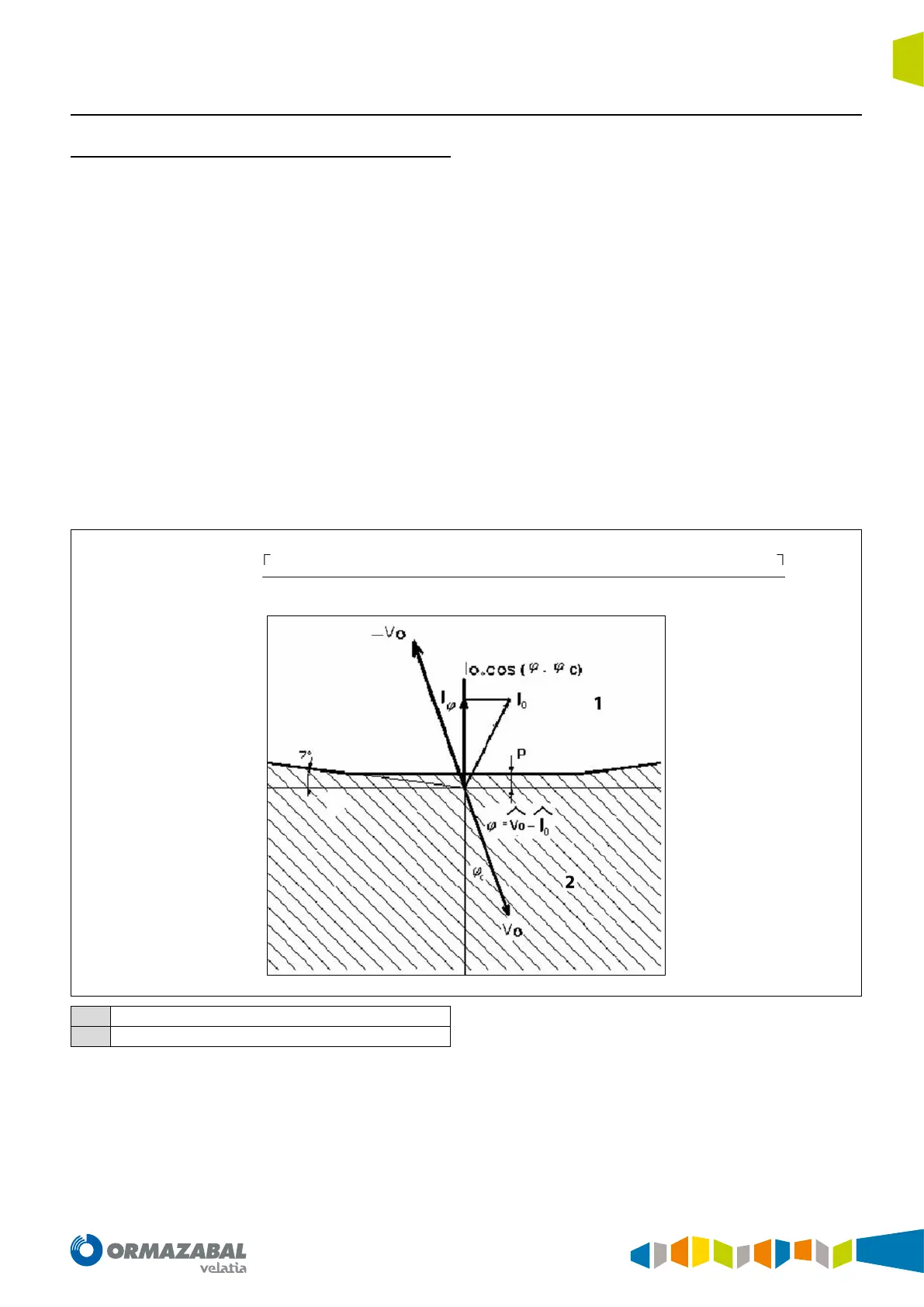
The trip zone depends on the angle between the zero-
sequence voltage and the zero-sequence pole current. In
the trip zone, the directional allows the trip when the I
0
•cos
(j-j
c
) value exceeds the setting (in negative value).
(
v – i – φ
)
=
Re(V) ⋅ cos(φ) + Im(V) ⋅ sin(φ)
⋅ Re(I) +
Im(V) ⋅ cos(φ) – Re(V) ⋅ sin(φ)
⋅ Im(I)
1
Tripping zone
2
Locking zone
Figure 4.15. I*cos(φ) directional