65
3. Basic operations
3-5. PinP (picture in picture)
Another image can be combined with the background image.
This unit supports two PinP channels.
3-5-1. Selecting the PinP channel and material
Press the [PinP 1/2] button among the AUX bus selector buttons.
When the button is lit in amber, the PinP1 sub menu is displayed on the LCD, and the state in which the PinP1
materials are selected is now established for the AUX bus crosspoint buttons.
When the button is lit in green, the PinP2 sub menu is displayed on the LCD, and the state in which the PinP2
materials are selected is now established for the AUX bus crosspoint buttons.
The selected AUX bus crosspoint button lights in amber. (It will light in red if the selected signal is a PGM output
signal.)
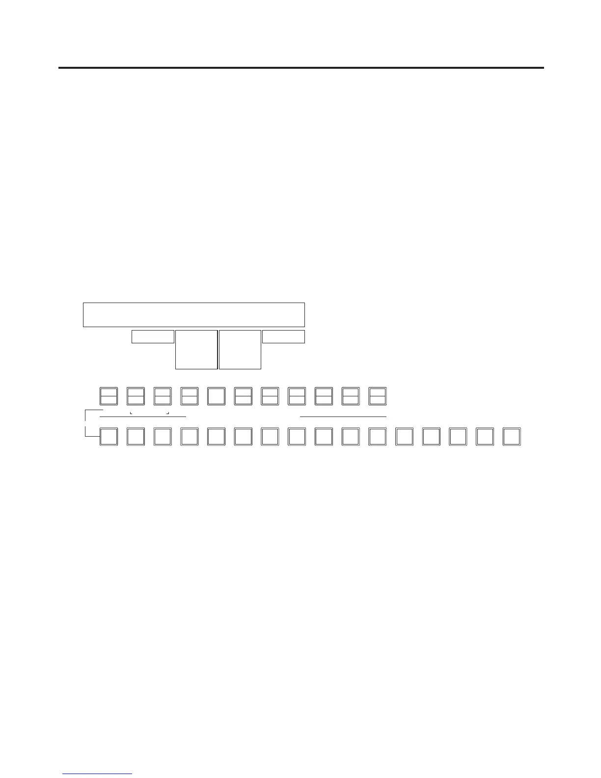
<Menu display>
PinP1 1
|
Shape
|
CrclAsp
|
Density
|
PVW
PinP1 | Square| 0.0| 100.0| Off
Circle 0.0
|
100.0
0.0
|
100.0
On