17
1. Installation
1-4. Connections
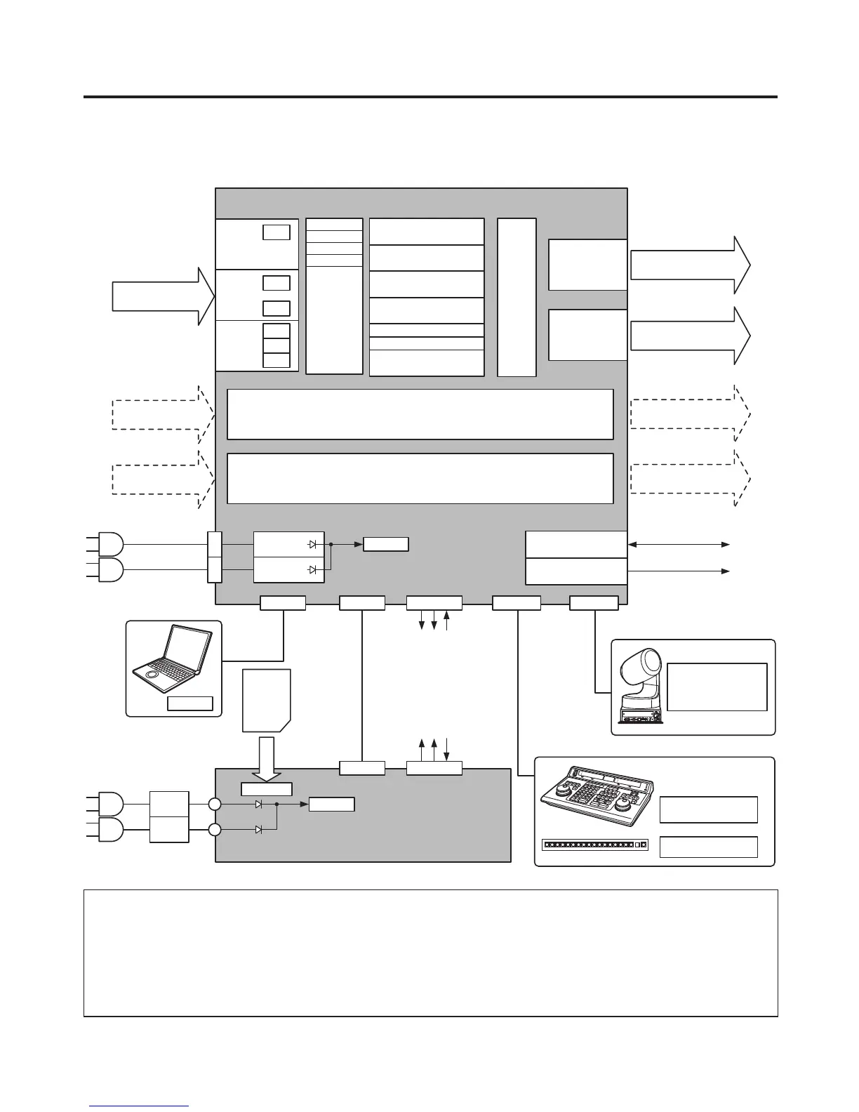
1-4-1. Block diagram
EDITOR COM
Editing
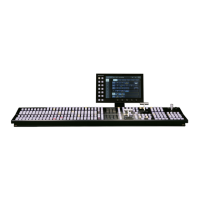
controller
Camera
Pan/Tilt Head
Controller
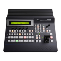
Aux panel
Mainframe
INPUT
1 to 8
FS
INPUT
9 to 12
FS
CC
INPUT
13 to 16
FS
UC
CC
INPUT (SDI)
1 to 16
INPUT
A1, A2
INPUT
B1, B2
Black
FMEM1
to 4
MTX
ColorBar
ColorBGD
BKGD
CUT, MIX, WIPE, DVE2
KEY
CUT, MIX, WIPE, DVE
AUX1
to 4
FTB
MV1, 2
DSK1, 2
MIX
PinP1, 2
MIX
OUTPUT
1 to 4
OUTPUT
5, 6
Output
MTX
OUTPUT (SDI)
1 to 4 (3)
OUTPUT (DVI-D)
5, 6
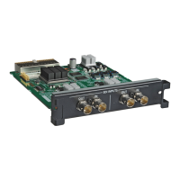
Option slot A
Option slot B
OUTPUT
A1, A2
OUTPUT
B1, B2
AC IN
PowerAC/DC
AC/DC
REF IN/OUT (1)
REF O UT (2)
RJ45
LAN
(5)
PANEL
(4)
TALLY/GPI
RJ45 Dsub 50 Dsub 9 Dsub 9
PC
SD
memory
card
REF
ALARM: 1
GPI-OUT: 31
GPI-IN: 8
ALARM: 1
GPI-OUT: 8
GPI-IN: 8
TALLY/GPIMAINFRAME
RJ45 Dsub 25
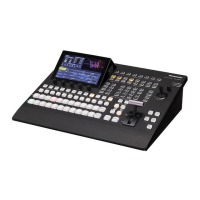
Control panel
DC IN
PowerAC/DC
AC/DC
1: When external synchronization is selected as the
reference signal setting, the reference signal is input.
When internal synchronization is selected, the reference
signal is output.
2: When external synchronization is selected as the
reference signal setting, the signals are looped through
and output. When internal synchronization is selected, the
reference signal is output.
3: Two sets of the same output signals are distributed from
OUTPUT (SDI) 1.
4: Connect the PANEL connector directly to the
MAINFRAME connector using the supplied CAT5E cable.
5: Do not connect to a public line when connecting a PC.





 To Next Page