97
4. Input/output signal settings
4-1. Input signal settings
IN1 to IN16 are SDI signal inputs.
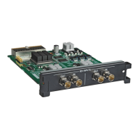
IN A1, IN A2, IN B1 and IN B2 can be set only when one of the following option boards has been connected.
AV-HS04M1 (SDI Input Board)
AV-HS04M2 (Analogue Input Board)
AV-HS04M3 (DVI Input Board)
AV-HS04M6 (Analogue Composite Input Board)
AV-HS04M8 (Full-HD DVI Input Board)
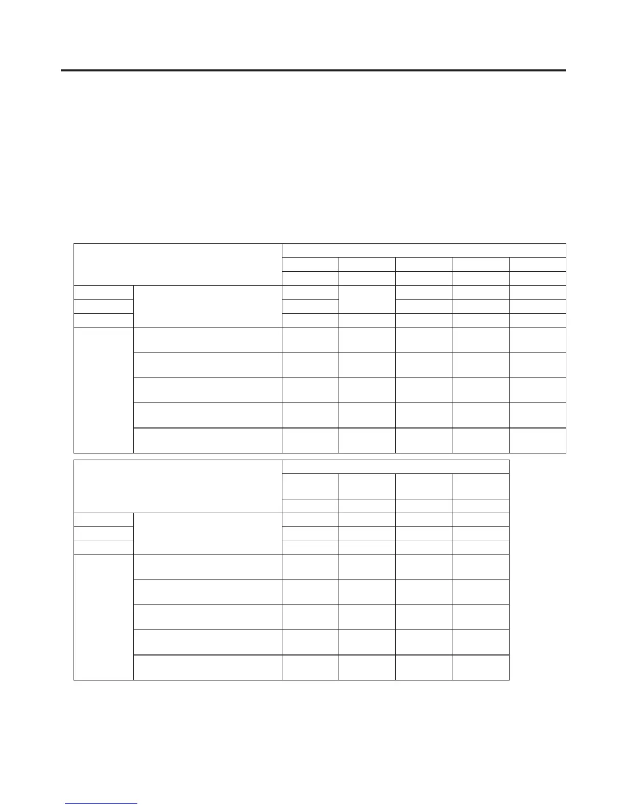
<List of settings by input signal>
Input connector
Setting menu and numbers of sections in this manual
FS Mode Freeze ColCor UpConv
4-1-1 4-1-2 4-1-3 4-1-4 4-1-5
IN1 to IN8
Standard
SDI input 16 lines
Only DbyD
selectable
——
IN9 to IN12
—
IN13 to IN16
Option slot
IN A1,
IN A2,
IN B1,
IN B2
AV-HS04M1
SDI input 2 lines
—
AV-HS04M2
Analogue component input 2 lines
—
AV-HS04M3
DVI-I input 2 lines
——
——
AV-HS04M6
Analogue composite input 2 lines
—
AV-HS04M8
DVI-D input 2 lines
——
——
Input connector
Setting menu and numbers of sections in this manual
AnaGain Setting
DVIIn
(Dig)
DVIIn
(Ana)
4-1-6 4-1-7 4-2 4-2
IN1 to IN8
Standard
SDI input 16 lines
————
IN9 to IN12 — — — —
IN13 to IN16 — — — —
Option slot
IN A1,
IN A2,
IN B1,
IN B2
AV-HS04M1
SDI input 2 lines
————
AV-HS04M2
Analogue component input 2 lines
———
AV-HS04M3
DVI-I input 2 lines
——
AV-HS04M6
Analogue composite input 2 lines
——
AV-HS04M8
DVI-D input 2 lines
——
—
: Can be set.
—: Cannot be set.