13.1.2. DIGITAL BOARD (PCB1): BOTTOM VIEW
13.2. ANALOG BOARD (PCB2)
13.2.1. ANALOG BOARD: COMPONENT VIEW
13.2.2. ANALOG BOARD: BOTTOM VIEW
13.3. OPERATION BOARD (PCB3)
13.3.1. OPERATION BOARD : COMPONENT VIEW
13.3.2. OPERATION BOARD : BOTTOM VIEW
13.4. SENSOR BOARD (PCB5)
13.5. POWER SUPPLY BOARD (PCB4)
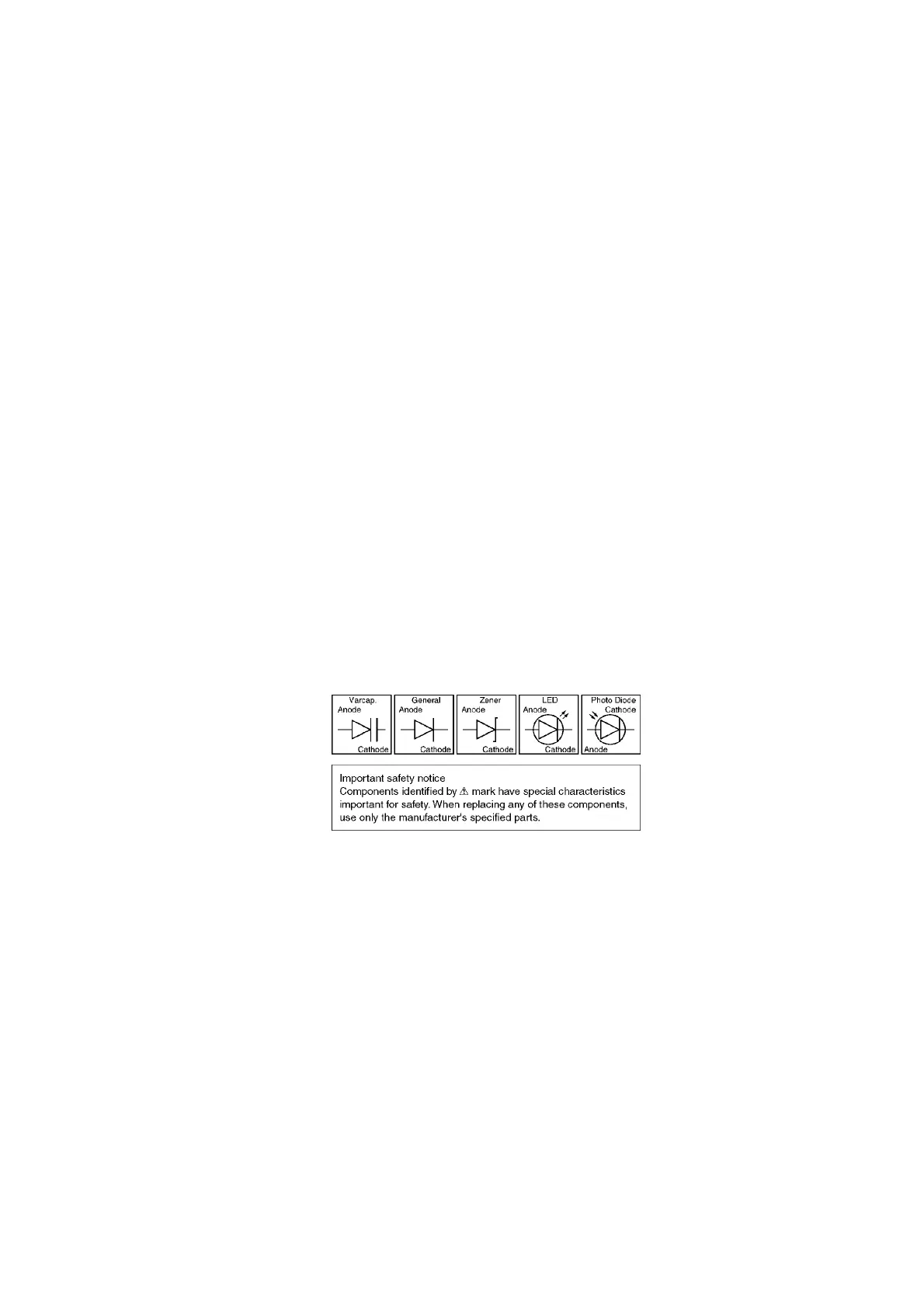
14. FOR THE SCHEMATIC DIAGRAMS
Note:
1. DC voltage measurements are taken with an oscilloscope or a
tester with a ground.
2. The schematic diagrams and circuit board may be modified at any
time with the development of new technology.
15. SCHEMATIC DIAGRAM
15.1. ANALOG BOARD (PCB2)
15.2. DIGITAL BOARD (PCB1)
15.3. OPERATION BOARD (PCB3)
15.4. POWER SUPPLY BOARD (PCB4)
15.5. SENSOR BOARD (PCB5)
Y.M / KXFP342CX /
227