Chapter 4 Settings — [DISPLAY OPTION] menu
106 - ENGLISH
Note
f Setting is also available from [FUNCTION BUTTON] (x page 121).
f Waveform monitor cannot be displayed in [P IN P].
f The waveform monitor turns off when [P IN P] is executed during waveform monitoring.
f The waveform monitor is not displayed when on-screen display is hidden (off).
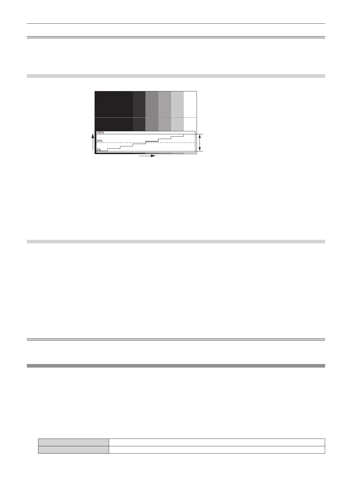
Adjusting the waveform
Project the luminance adjustment signal of a commercial test disk (0 % (0 IRE or 7.5 IRE) – 100 % (100 IRE)) and adjust.
Signal level
Image displayable area
Screen position
1) Select “Select line (luminance)” on the waveform monitor.
2) Adjust black level.
f Use [BRIGHTNESS] in the on-screen menu [PICTURE] to adjust the black level 0 % of the video signal to the 0 % position of the
waveform monitor.
3) Adjust white level.
f Use [CONTRAST] in the on-screen menu [PICTURE] to adjust the white level 100 % of the video signal to the 100 % position of the
waveform monitor.
Adjusting red, green, and blue
1) Set [COLOR TEMPERATURE] to [USER1] or [USER2] (x page 72).
2) Select “Select line (red)” on the waveform monitor.
3) Adjust dark red areas.
f Use [RED] in [WHITE BALANCE LOW] to adjust the black level 0 % of the video signal to the 0 % position of the waveform monitor.
4) Adjust bright red areas.
f Use [RED] in [WHITE BALANCE HIGH] to adjust the white level 100 % of the video signal to the 100 % position of the waveform
monitor.
5) Use the procedure for [RED] to adjust [GREEN] and [BLUE].
Note
f For DVI-D signal, HDMI signal, SDI signal, and DIGITAL LINK signal, conrm that the [SIGNAL LEVEL] setting is correct before start
adjusting the black level.
[CUT OFF]
Each red, green, and blue color component can be removed.
1) Press as to select [CUT OFF].
2) Press the <ENTER> button.
f The [CUT OFF] screen is displayed.
3) Press as to select [RED], [GREEN], or [BLUE].
4) Press qw to switch the item.
[OFF] Disables cutoff.
[ON] Enables cutoff.
 Loading...