Chapter 6 Appendix — Technical information
172 - ENGLISH
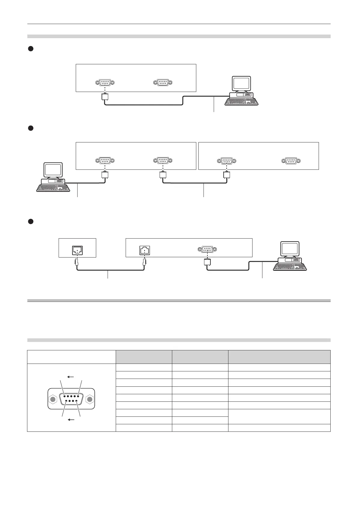
Connection
Projector connecting terminals
Computer
D-Sub 9p (female) D-Sub 9p (male)
D-Sub 9p (male)
Communication cable (straight)
Single projector
Multiple projectors
Connecting terminals on projector 2
D-Sub 9p (female) D-Sub 9p (male)
D-Sub 9p (female) D-Sub 9p (male)
Connecting terminals on projector 1
Computer
D-Sub 9p (male) D-Sub 9p (female)
D-Sub 9p (male)
Communication cableCommunication cable
DIGITAL LINK compatible device
Computer
D-Sub 9p (female)
Projector connecting terminals
DIGITAL LINK DIGITAL LINK
D-Sub 9p (male)
Communication cable (straight)
When connecting with the DIGITAL LINK compatible devices
LAN cable (straight)
Note
f The destination of [RS-232C] (x page 118) must be set according to the connection method.
f When connecting by a DIGITAL LINK compatible device, set the [PROJECTOR SETUP] menu → [STANDBY MODE] (x page 116) setting
to [NORMAL] to control the projector during standby.
When [STANDBY MODE] is set to [ECO], the projector cannot be control during standby.
Pin assignments and signal names
D-Sub 9-pin (female)
Outside view
Pin No. Signal name Details
(9) (6)
(5) (1)
(1) ― NC
(2) TXD Transmitted data
(3) RXD Received data
(4) ― NC
(5) GND Earth
(6) ― NC
(7) CTS
Connected internally
(8) RTS
(9) ― NC
 Loading...