1 Applicable signals 4
2 Safety Precautions
5
2.1. General Guidelines
5
3 Prevention of Electro Static Discharge (ESD) to
Electrostatically Sensitive (ES) Devices
6
4 About lead free solder (PbF)
7
5 Service Hint
8
6 Disassembly
9
6.1. Removal of the Back Cover
9
6.2. Removal of the HA-Board
9
6.3. Removal of the Slot Block
9
6.4. Removal of the J-Board
10
6.5. Removal of the HX-Board
10
6.6. Removal of the DA-Board
11
6.7. Removal of the P-Board
11
6.8. Removal of the D-Board
11
6.9. Removal of the Speaker (L, R)
11
6.10. Removal of the SU-Board and the SD-Board
12
6.11. Removal of the SC-Board
12
6.12. Removal of the SS-Board
13
6.13. Removal of the C1, C2-Board
13
6.14. Removal of the S-Board
14
6.15. Removal of the GK-Board
14
6.16. Removal of the K-Board
14
6.17. Removal of the Control Panel, the Power SW and the
Door
15
6.18. Removal of the Front Glass
15
6.19. Removal of the Escutcheon
16
6.20. Removal of the Plasma Panel
18
7 Location of Lead Wiring
20
7.1. Location of Lead Wiring (1)
20
7.2. Location of Lead wiring (2)
21
7.3. Location of Lead wiring (3)
22
7.4. Location of Lead Wiring (4)
23
8 Adjustment Procedure
24
8.1. Driver Set-up
24
8.2. Initialization Pulse Adjust
25
8.3. P.C.B. (Printed Circuit Board) exchange
25
8.4. Adjustment Volume Location
26
8.5. Test Point Location
27
9 Service mode
28
9.1. CAT (computer Aided Test) mode
28
9.2. IIC mode structure (following items value is sample data.)
31
10 Adjustment
32
10.1. RGB white balance adjustment
32
10.2. HD white balance adjustment
34
10.3. Power control adjustment
36
11 Troubleshooting guide
37
11.1. Self Check
37
11.2. No Power
39
11.3. No Picture
39
11.4. Local screen failure
40
12 Option Setting
41
R
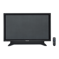
×H×D) 917 mm × 644 mm × 95 mm 1,020 mm ×705 mm × 95 mm
(109 mm when including protruding portion of slots)
(37 inch)
(109 mm when including protruding portion of slots)
(42 inch)
Mass (weight) approx. 26.0 kg net (37 inch) approx. 30.0 kg net (42 inch)
Sound
Speaker 120 mm × 60 mm × 2 pcs, 8-ohm