26
6K Hardware Installation Guide
RS-485 Communication
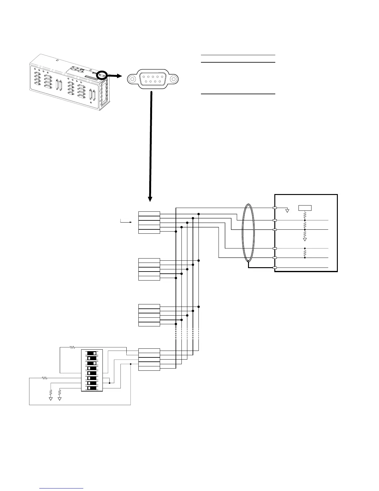
RS-232/485 Connector
1
male
5
69
PIN OUTS FOR RS-485 COMMUNICATION
Pin Description
1 Rx + (also called RD B)
4 Tx + (also called TD B)
6 GND (isolate ground)
7 Rx – (also called RD A)
8 Tx – (also called TD A)
•
Maximum RS-485 cable length is 4000 feet (1220 meters).
•
To establish unique addresses for multi-drop units, use the
ADDR
command.
•
Use termination resistors at both ends of the multi-drop. Keep
stubs as short as possible.
•
Recommended cables: 2-wire: Belden 9841
4-wire: Belden 9842
•
Refer to the diagrams below (or page 5) for necessary DIP
switch settings for 2-wire and 4-wire configuration.
4-Wire Connections (plus ground):
RS-232/485
connector
Master Unit
Tx+
Tx
Rx+
Rx
120 W
120 W
Shield
Unit #1
Unit #2
Unit #3
Unit #31
120 W
681W
120 W
The DIP switch shown above is configured for RS-485 4-wire.
DIP switches 1-4 select internal resistor values (ON selects the resistor).
Use these resistors only for the last unit (or for a single unit).
Refer to page 5 for instructions on how to access and set the switches.
+5VDC
Ground
681W
1
2
3
4
5
6
7
8
O
N
Pin 1 (Rx+)
Pin 7 (Rx-)
Pin 4 (Tx+)
Pin 8 (Tx-)
Pin 6 (GND)
Pin 1 (Rx+)
Pin 7 (Rx-)
Pin 4 (Tx+)
Pin 8 (Tx-)
Pin 6 (GND)
Pin 1 (Rx+)
Pin 7 (Rx-)
Pin 4 (Tx+)
Pin 8 (Tx-)
Pin 6 (GND)
Pin 1 (Rx+)
Pin 7 (Rx-)
Pin 4 (Tx+)
Pin 8 (Tx-)
Pin 6 (GND)