EasyManuals Logo

Parker AC10 series Quick Start Guide

Parker AC10 series
60 pages
To Next Page IconTo Next Page
To Previous Page IconTo Previous Page
Page #14 background imageLoading...
Page #14 background image
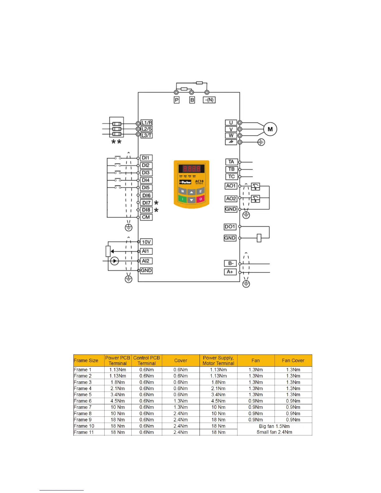
Braking Unit (Optional)
1/3 Phase Input
230/480VAC
50/60Hz
Digital Input
Terminals
Analog Inputs
2.2kΩ/1W
0-20mA
Analog Output1
0-10V
Relay Output
5A/230VAC or 30VDC
Multifunction Output
(24 VDC)
Modbus
Communications
*
IP66 drives have 6 digital inputs
**
Refer to appendix for fuse sizing
Braking Resistor (Optional)
2-9 Connections
Terminal Tightening Torques
This illustration is for reference only
and may not show the connections for
your specic drive. Please refer to the
Product Installation Manual for detailed
connection diagram.
Simplified Connection Diagram

Other manuals for Parker AC10 series

Questions and Answers:

Question and Answer IconNeed help?

Do you have a question about the Parker AC10 series and is the answer not in the manual?

Parker AC10 series Specifications

General IconGeneral
Overload Capacity150% for 60 seconds
Analog Inputs2
Analog Outputs1
Communication OptionsModbus RTU
Protection RatingIP20
Input Voltage200-240VAC, 380-480VAC, 500-575VAC, 600VAC, 690VAC
Digital Outputs2
ProtectionOvercurrent, Overvoltage, Undervoltage, Overtemperature, Short Circuit
Operating Temperature-10°C to +50°C
Humidity5% to 95% (non-condensing)
DimensionsVaries by model
WeightVaries by model
BrakingBuilt-in dynamic braking

Related product manuals