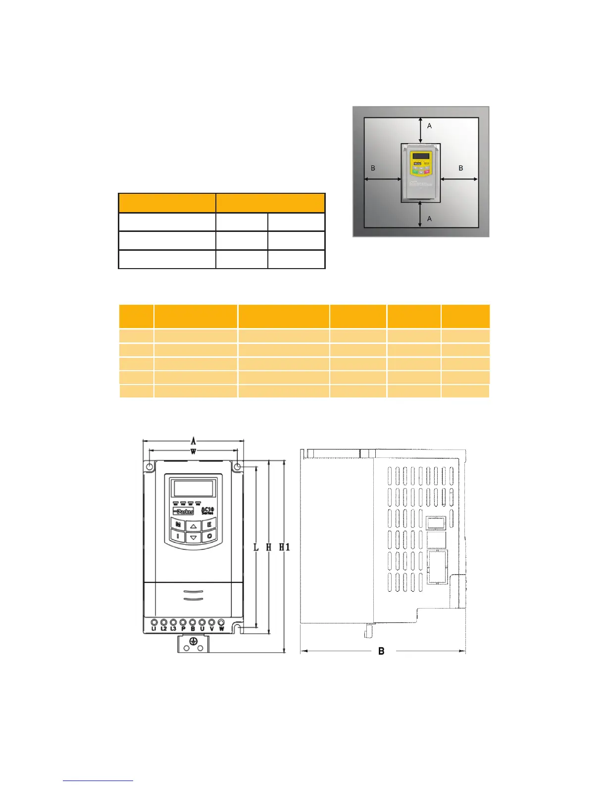
Installation
Inverter should be installed vertically, as shown in
Figure 7-1. Sufcient ventilation space should be
ensured in its surrounding.
Clearance dimensions (recommended) are
available from Table 7-1 Clearance Dimensions for
installing of the inverter. Space between 2 drives
25mm.
IP20
Frame
Part Number
External Dimension
AxBxH (H1) [mm]
Weight [lb/
kg]
Mounting
Size (WxL)
Mounting
Bolt
1 10G-X1-XXXX-XX 80×135×138 (153) 2.76/1.25 70×128 M4
2 10G-X2-XXXX-XX 106×150×180 (195) 3.88/1.76 94×170 M4
3 10G-43-XXXX-XX 138×152 ×235 (250) 6.53/2.96 126×225 M5
4 10G-44-XXXX-XX 156×170×265 (280) 10.80/4.9 146×255 M5
5 10G-45-XXXX-XX 205×196 ×340 (355) 16.53/7.5 194×330 M5
Note: H is the size of inverter without grounding plate. H1 is the size of inverter with grounding plate.
Model Clearance Dimensions
IP20 Plastic
A ≥150mm B ≥50mm
IP20 Metal
A ≥200mm B ≥100mm
IP66
A ≥150mm B ≥12.5mm
IP20 Plastic Enclosure - Frame 1-5
Dimensions
2-5 Installation and Dimensions

 Loading...


