128
APEX615n Installation Guide
By changing the move profile—less torque, slower velocities, or a longer time between
moves, for example—you may be able reduce the regeneration to a lower level, so that the
fault no longer occurs.
By installing an external resistor, you can double the regeneration circuit’s power dissipation
capabilities. With the resistor installed, the circuit’s specifications become:
Continuous Power
Dissipation Rating
Peak Power
Dissipation Rating
APEX6151 100 watts
2 KW
APEX6152 N/A
N/A
APEX6154 180 watts
12 KW
After you alter the move profile, or install the external resistor, run the system again to verify
that regeneration no longer causes a fault.
Calculation Methods
You can use the calculation method to predict peak power dissipation and average power
dissipation. If peak power is greater than one kilowatt, or average power is greater than 50W,
you should install an external regeneration resistor.
A NOTE ABOUT UNITS: We want a solution for power that is express in watts. To be
consistent, we will use SI (metric) units in the following equations. If you want to use other
units, apply conversion factors in the appropriate places.
Calculating Peak Power
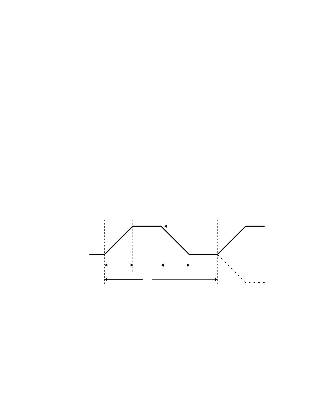
A typical trapezoidal move profile is shown below.
Time
Velocity
t
1
Acceleration
t
2
t
1
Deceleration
V
max
(in rps)
Move Profile for Regeneration Calculations
Regeneration only occurs during the deceleration portion of the move. At any moment during
deceleration, the amount of power regeneration is equal to the shaft power:
P
shaft
=
ω
T = 2πvT
where
T = torque, in newton meters (Nm)
ω
= shaft velocity, in radians per second
v = shaft velocity, in revolutions per second (rps)
Artisan Technology Group - Quality Instrumentation ... Guaranteed | (888) 88-SOURCE | www.artisantg.com

 Loading...


