10
APEX615n Installation Guide
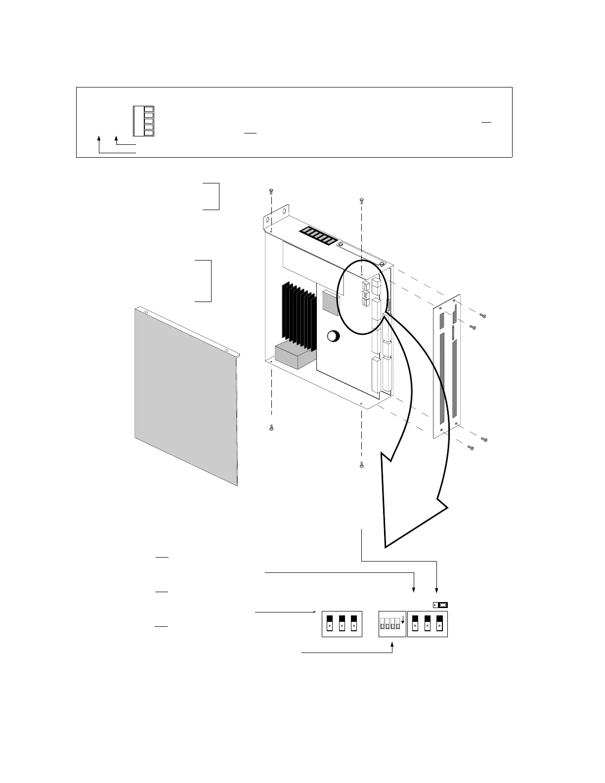
Changing the COM 2 Connector from RS-232 to RS-485
Rx+
Rx–
Tx+
Tx–
Iso Gnd
RS-232 (factory default)
RS-485
optional
COM 2
Rx
Tx
Shld
+5V
Iso
Gnd
RS-232C Users
The APEX615n's COM 2 port is factory configured for RS-232C
communication (use the right-hand pin descriptions). If you
do
not need to use RS-485 communication, you may ignore this
section and proceed to the
Mounting
instructions.
O
N
1234
12
3
JU2
SW2
SW1 SW3
123
1.
Remove the four retainer screws
from the faceplate. Gently lift
away the faceplate .
2.
Step 2 is only necessary for
the APEX6151. Skip to Step 3
for APEX6152 & 6154.
Remove the four retainer
screws from the side panel, and
pull the panel away.
(two on the top of chassis,
two on the bottom of chassis)
Be careful not to catch
the 50-pin header clips
on the faceplate.
DIP switch #4: Rx Termination Resistor...........120 Ω
DIP switch #3: Tx+ Bias Resistor.....................681 Ω
DIP switch #2: Tx Termination Resistor...........120 Ω
DIP switch #1: Tx– Bias Resistor.....................681 Ω
NOTE: Set the switches of SW1 to ON (as illustrated) to use the internal resistors. Typically do this for a single
unit or for the last unit in a multi-drop. If these resistor values are not appropriate for your application, set the
switches to OFF and connect your own external resistors. See page 25 for resistor calculations and wiring
instructions.
*4-wire = full duplex (transmit and receive at the same time); 2-wire = half-duplex (transmit or receive at any time);
COM 2 port for RS-232: Leave JU2 set to position 1 (factory default).
COM 2 port for RS-485: Set jumper JU2 to position 3 on all units, as illustrated.
(disables power-up messages, error messages, & echo).
3.
Set the jumper.
4.
Set the DIP switches.
Switches and jumper shown configued for RS-485, 4-wire.
5.
Reattach the side panel and faceplate and replace the retainer screws.
SW1
SW3
(Rocker-style switch — depress raised side of switch to change states. Shown in ON position.)
DIP switch #3: OFF= 2-wire, ON= 4-wire*
DIP switch #2: Turn ON for RS-485
DIP switch #1: Turn ON for RS-485
SW2
(Rocker-style switch — depress raised side of switch to change states. Shown in ON position.)
DIP switch #3: Turn ON for RS-485
DIP switch #2: Turn ON for RS-485
DIP switch #1: Turn ON for RS-485
1
3
Artisan Technology Group - Quality Instrumentation ... Guaranteed | (888) 88-SOURCE | www.artisantg.com

 Loading...


