40
APEX615n Installation Guide
Resolver Connector
Connect the motor end of the resolver cable to the motor. Cables are available for SM motors
in 10 and 25 foot lengths; and for APEX Series motors in 10, 25, 50, and 100 foot lengths.
The cables have MS-type connectors on the motor end of the cable. You can also order custom
cables of any length. Call Compumotor's Customer Service Department at the phone numbers
provided on the inside front cover of this document.. Cable lengths in excess of 100 feet are
not recommended.
Plug the drive end of the cable into the APEX615n's resolver input connector. (The drive end
of the cable should already be wired to the removable 13-pin resolver connector, as shown
below. The connector can accept wires as large as 12 AWG (4 mm
2
).)
Shield
Stator 3
Stator 1
Stator 2
Stator 4
Rotor 1
Rotor 2
Motor Temp+
Motor Temp -
Fault Relay+
Fault Relay -
No Connection
No Connection
Function
Uninsulated
Red
Black
Green
Blue
Brown
White
Yellow
Orange
APEX Cable
Color Code
Uninsulated
Red
Black
Green
Blue
Brown
White
Yellow
Yellow
SM Cable
Color Code
Shield
Red
Black
Green
Blue
Brown
White
MT+
MT -
Flt Relay+
Flt Relay -
NC
NC
Ref
Sin
Cos
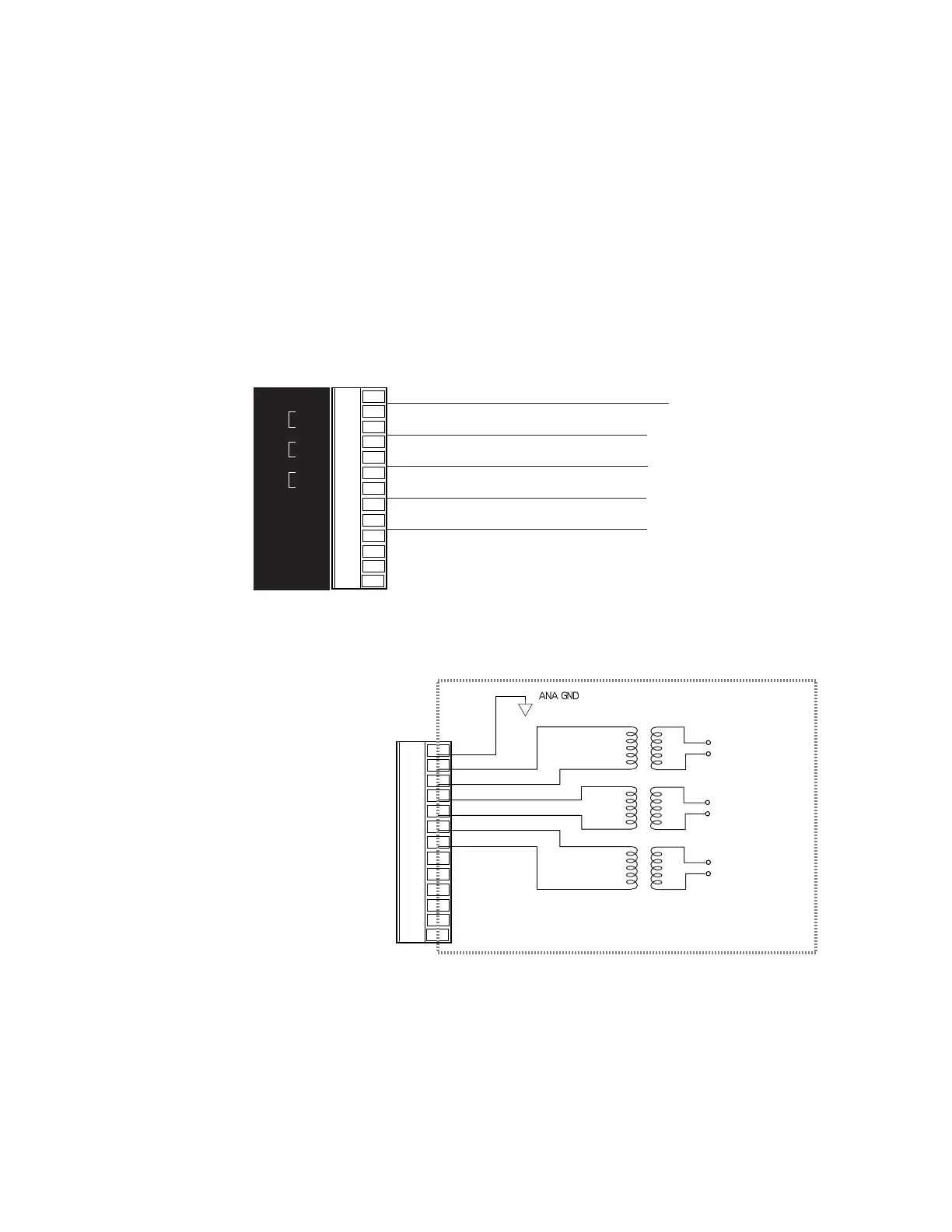
Schematic diagrams of each input and output on the resolver connector are shown below.
RESOLVER Connector
Shield
Red
Black
Green
Blue
Brown
White
MT+
MT -
Flt Relay+
Flt Relay -
NC
NC
Stator Input Voltage:
2V r
ms ± 5%
Internal Schematic
1:1
4.25V rms ± 5%
at 7 kHz ± 5%
(sine wave)
To RDC
To RDC
1:1
1:1
DIP Switch #3, position 4, must be OFF so that:
• Internal microprocessor uses resolver information for commutation
• Encoder output will be enabled
• Hall Effect input will be disabled
Artisan Technology Group - Quality Instrumentation ... Guaranteed | (888) 88-SOURCE | www.artisantg.com

 Loading...


