Chapter 1. Installation
25
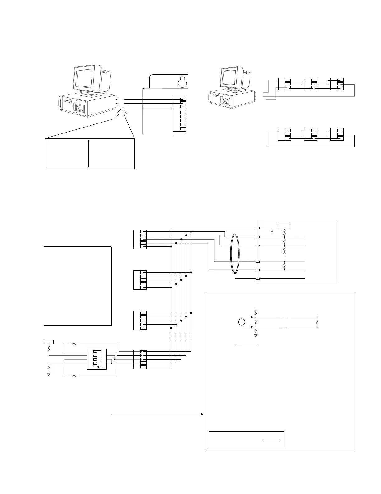
Serial Communication
Rx
Tx
Iso GND
COM 1
COM 2
Rx
Tx
SHLD
+5V
Iso
GND
Rx+
Rx–
Tx+
Tx–
Iso GND
Rx
Tx
Iso GND
RS-232C Connections
Standard 25-Pin
COM Port Pin Outs:
Pin 2 = Transmit (Tx)
Pin 3 = Receive (Rx)
Pin 7 = Ground (GND)
Standard 9-Pin
COM Port Pin Outs:
Pin 3 = Transmit (Tx)
Pin 2 = Receive (Rx)
Pin 5 = Ground (GND)
Serial Port Connection
Tx
Rx
GND
RS-232C Daisy-Chain Connections*
Unit 0
Rx
Tx
Iso GND
Unit 1
Rx
Tx
Iso GND
Unit 2
Tx
Rx
GND
Daisy Chain to a Computer or Terminal
Rx
Tx
Iso GND
Unit 0
Rx
Tx
Iso GND
Unit 1
Rx
Tx
Iso GND
Unit 2
Stand-Alone Daisy Chain
Be sure to set unique devices addresses for each unit using the
ADDR command (see
6000 Series Software Reference
).
*
NOTE: Maximum RS-232C cable length is 50 feet (15.25 meters)
Rx+
Rx–
Tx+
Tx–
Iso GND
COM 2
Rx+
Rx–
Tx+
Tx–
Iso GND
Rx+
Rx–
Tx+
Tx–
Iso GND
Rx+
Rx–
Tx+
Tx–
Iso GND
Rc
Vcc
Rd
Vb Rb
Balanced Cable.
Ra
Step 1 Calculate the equivalent resistance (Req)
*
of Rc / / Rb:
Rc / / Rb = 120Ω / / 120Ω = 60Ω
Step 2 Calculate the pull-up and pull-down resistor values knowing that
the FAILSAFE bias is 200mV and Vcc = 5V:
Vb = Vcc (Req / (Ra + Req + Rd))
solving for R' (defined as Ra + Rd)
R' = ((Req) Vcc / Vb) - Req
R' = ((60Ω) 5V / 0.2V) - 60Ω = 1440Ω
Since Ra and Rd are equal, Ra = Rd = 1440Ω / 2 = 720Ω
Step 3 Recalculate the equivalent resistance of RC / / (Ra + Rd):
Rc / / (Ra + Rd) = 120Ω / / (720Ω + 720Ω) = 110.77Ω
Since the equivalent resistance is close (within 10%) to the characteristic
impedance of the cable (Zo), no further adjustment of resistor values is
required.
Example
Assumptions: The cable's characteristic impedance (Zo) = 120Ω.
Rc and Rb are equal and are selected to match Zo
(Rc = Rb = Zo = 120Ω).
For further information,
consult a communications
interface reference.
* Actual calculation
for equivalent resistance
(e.g., R
1
/ / R
2
):
R
1
R
2
(R
1
+ R
2
)
RS-485 Connections (4-wire interface)
Master
UnitTx+
RS-485 Configuration
Before you can use RS-485
communication, you must re-
configure the COM 2 port by
setting internal jumper JU2 to
position 3, and setting DIP
switches 1-3 on SW2 and DIP
switches 1-2 on SW3 to the ON
position. Set DIP switch 3 on
SW3 to ON position for 4-wire
interface (2-wire is default, using
Tx+ and TX- terminals on COM2
port).
Refer to page 10 for instructions.
Tx–
Rx+
Rx–
120 Ω
120 Ω
Shield
Unit #1
Unit #2
Unit #3
Unit #31
DIP switch selects internal resistor values (ON selects the resistor).
Use these resistors only for the last unit (or for a single unit).
If your application requires terminating resistors other than 120Ω,
and/or bias resistors other than 681Ω, then make sure the internal
DIP switches are set to OFF and connect your own external resistors.
To calculate resistor values:
5VDC
120 Ω
681Ω
Calculating Resistor Values
681Ω
12
34
O
N
120 Ω
+5VDC
NOTE: Maximum RS-485 cable length is 4000 feet (1220 meters)
COM 2
COM 2COM 2
Iso GND
Iso Gnd
Artisan Technology Group - Quality Instrumentation ... Guaranteed | (888) 88-SOURCE | www.artisantg.com

 Loading...


