Chapter 1. Installation
37
Encoder Output Connector
The encoder output connector is a dual use connector. It can be used for either Encoder Output
or for Hall Effect Input. Use DIP Switch #3, position 4, to select desired function.
OFF = Encoder Output (derived from the resolver input)
ON = Hall Effect Input mode
Hall E
ect Input
Pin #:
1
2
3
4
5
6
7
Function:
No Connect
No Connect
Hall +5VDC
Hall 1
Hall 2
Hall 3
Hall Ground
Encoder Output
Pin #:
1
2
3
4
5
6
7
Function:
Channel A+
Channel A–
Channel B+
Channel B–
Channel Z+
Channel Z–
Ground
CHA+
CHA -
CHB+
CHB -
CHZ+
CHZ -
Gnd
Encoder Output
Schematic diagrams of the Encoder Output circuit and of the Hall Effect Input circuit are
shown in the next sections.
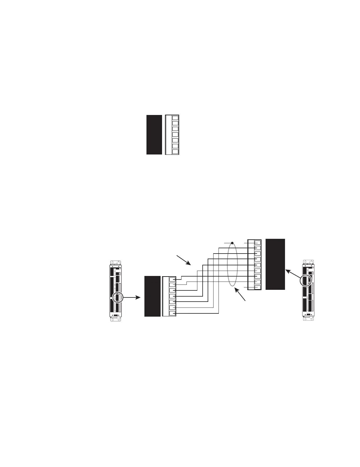
Encoder Output to
External Devices
The encoder output can be used to send information to an external device. In multi-axis
applications, for example, with APEX615ns running in following mode, you can connect the
encoder output from the master unit to the encoder input of the slave unit, as shown in the
next drawing. See the Programmer's Guide for details.
APEX6151
APEX6151
CHA+
CHA -
CHB+
CHB -
CHZ+
CHZ -
Gnd
Encoder Output
Shield
Iso Gnd
Z -
Z+
B -
B+
A -
A+
+5V
NC
NC
External Encoder Input
Connect CHA+ to A– (note polarity)
CHA- to A+ (note polarity)
Connect CHB+ to B+
CHB- to B-
CHZ+ to Z+
CHZ- to Z-
Gnd to Iso Gnd
Do not connect shield
MASTER SLAVE
Artisan Technology Group - Quality Instrumentation ... Guaranteed | (888) 88-SOURCE | www.artisantg.com

 Loading...


