6
APEX615n Installation Guide
Pre-installation Adjustments
DIP Switch Settings – Motor Current, Feedback Options, Drive Features
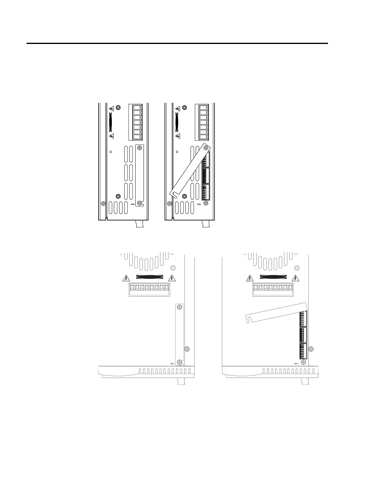
The APEX615n has three 8-position DIP switches. The switches are located behind a small
metal cover on top of the APEX615n. Loosen the two screws that hold the access cover.
Move the cover out of the way to expose the DIP switches.
123456781234567812345678
DANGER
L1
L2
Earth
Earth
Earth
Control L1
Control L2
HIGH VOLTAGE
OFF
18
SW1
18
SW2
18
SW3
123456781234567812345678
DANGER
L1
L2
Earth
Earth
Earth
Control L1
Control L2
HIGH VOLTAGE
OFF
18
SW1
18
SW2
18
SW3
APEX6151 DIP Switch Location, with Cover Closed and Open
DANGER
HIGH VOLTAGE
L1
L2
L3
Earth
Earth
Control L1
Control L2
12345678
12345678
12345678
12345678
12345678
12345678
Off
1
SW1
8
1
SW2
8
1
SW3
8
Off
1
SW1
8
1
SW2
8
1
SW3
8
DANGER
HIGH VOLTAGE
L1
L2
L3
Earth
Earth
Control L1
Control L2
APEX6152/6154 DIP Switch Location, with Cover Closed and Open
The default setting for all DIP switches when the APEX615n ships from the factory is off.
You must set these switches to configure the drive for your particular application. Use a small
screwdriver to set the switches. The next section summarizes the function of each switch. See
Appendix F for additional description of DIP switch functions.
Artisan Technology Group - Quality Instrumentation ... Guaranteed | (888) 88-SOURCE | www.artisantg.com

 Loading...


