14
APEX615n Installation Guide
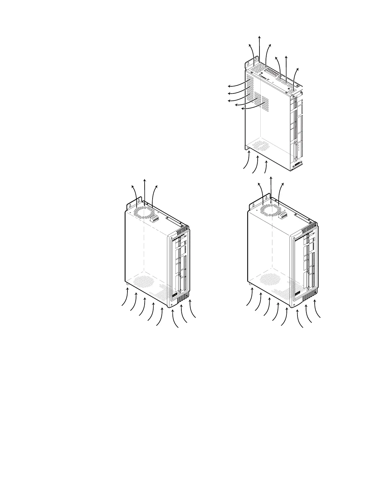
Airflow & Cooling
The APEX615n can operate in an
ambient temperature environment of 0°C
to 50°C (32°F to 122°F). It is cooled by
an internal fan mounted at the top of the
drive. The fan draws air in through the
bottom and upward over the internal
heatsink. The air directly beneath the
APEX615n must not exceed 50°C
(122°F).
The APEX615n does not have an air
filter. You must protect its intake air
supply from contamination.
DANGER
HIGH VOLTAGE
L1
L2
Earth
Earth
Earth
Control L1
Control L2
APEX6151
Compumotor
Offset
Balance
Tach OutputTach Output
Calibration
Torque CmdTorque Cmd
Test PointTest Point
Enable
Disable
Bridge FaultBridge Fault
Drive FaultDrive Fault
Motor FaultMotor Fault
Over VoltageOver Voltage
I
2
T Limit
Regen FaultRegen Fault
Regen ActiveRegen Active
Reset
Gnd
NC
Enable InEnable In
Fault OutFault Out
Gnd
NC
NC-
Tach OutTach Out
Gnd
+15V
Gnd
-15V
CHA+
CHA -CHA -
CHB+
CHB -CHB -
CHZ+
CHZ -CHZ -
Gnd
Shield
Red
Blk
Grn
Blu
Brn
Wht
M T +M T +
M T -M T -
Flt Relay+Flt Relay+
Flt Relay -Flt Relay -
NC
NC
Encoder Output
ANI+
ANI -ANI -
Trg-A
Trg-B
Out-A
Iso GndIso Gnd
+5V
Out-P
In-P
Aux-P
Auxiliary
Iso GndIso Gnd
Home
Neg
Pos
Limits
Shield
Iso GndIso Gnd
Z -
Z+
B -
B+
A -
A+
+5V
External Encoder Input
+5V
Iso GndIso Gnd
Rx
Tx
Shield
RP 240
Rx
Tx
Iso GndIso Gnd
RS 232
Programmable Inputs/Outputs
12
5049
Ref Sin Cos
APEX6151
Airflow
49 50
Programmable Inputs/Outputs
12
CHA+
CHA -
CHB+
CHB -
CHZ+
CHZ -
Gnd
Encoder Output
Shield
S1 Red
S2 Blk
S3 Grn
S4 Blu
R1 Brn
R2 W
ht
M
T+ Yel
M
T- Org
Flt Relay+
Flt Relay -
NC
NC
Reset
Gnd
NC
Enable In
Fault Out
Gnd
NC
NC
Tach Out
Gnd
+15 V
Gnd
-15 V
Enable
Disable
Bridge Fault
Drive Fault
M
otor Fault
Over Voltage
I
2
T Lim
it
Regen Fault
Regen Active
Shield
Gnd
Z -
Z+
B -
B+
A -
A+
+5V
Gnd
Hom
e
CCW
CW
ANI
AGnd
Trg-A
Trg-B
Out
Gnd
+5V
Out-P
In-P
Auxiliary Limits
External Encoder Input
+5V
Gnd
Rx
Tx
Shield
RP 240
RS 232
Rx
Tx
G
nd
ompumotor
ompumotor
49 50
Programmable Inputs/Outputs
12
CHA+
CHA -
CHB+
CHB -
CHZ+
CHZ -
Gnd
Encoder Output
Shield
S1 Red
S2 Blk
S3 Grn
S4 Blu
R1 Brn
R2 W
ht
M
T+ Yel
M
T- O
rg
Flt Relay+
Flt Relay -
NC
NC
Reset
Gnd
NC
Enable In
Fault Out
Gnd
NC
NC
Tach Out
Gnd
+15 V
Gnd
-15 V
Enable
Disable
Bridge Fault
Drive Fault
M
otor Fault
Over Voltage
I
2
T Lim
it
Regen Fault
Regen Active
Shield
Gnd
Z -
Z+
B -
B+
A -
A+
+5V
Gnd
Hom
e
CCW
CW
ANI
AGnd
Trg-A
Trg-B
Out
Gnd
+5V
Out-P
In-P
Auxiliary Limits
External Encoder Input
+5V
Gnd
Rx
Tx
Shield
RP 240
RS 232
Rx
Tx
Gnd
APEX6152 APEX6154
AirflowAirflow
Torque Cmd
Test Point
Offset
Balance
Tach Output
Calibration
Torque Cmd
Test Point
Offset
Balance
Tach Output
Calibration
Panel Layout
When designing the panel layout, remember that the APEX615n produces heat that must be
dissipated. Heat produced may be as high as:
• 100 watts for an APEX6151 operating continuously at 8 amps
• 150 watts for an APEX6152 operating continuously at 12 amps
• 200 watts for an APEX6154 operating continuously at 20 amps
The actual dissipation will vary depending on the application duty cycle, motor size, and load
inertia.
Panel layout dimensions are shown below.
Artisan Technology Group - Quality Instrumentation ... Guaranteed | (888) 88-SOURCE | www.artisantg.com

 Loading...


