Chapter 1. Installation
29
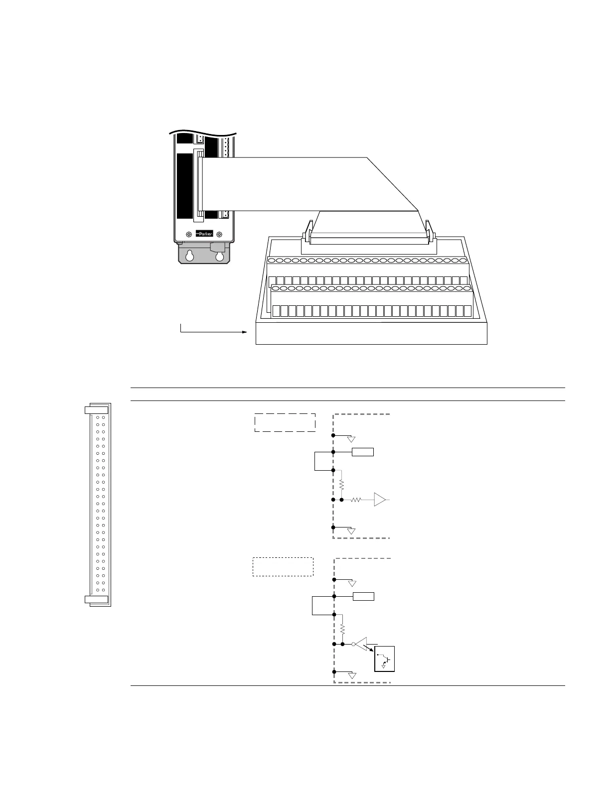
General-Purpose Programmable Inputs & Outputs
VM50 ADAPTOR —
for screw-terminal connections
CHA+
CHA -
CHB+
CHB -
CHZ+
CHZ -
Gnd
Shield
Red
Blk
Grn
Blu
Brn
Wht
M T +
M T -
Flt Relay+
Flt Relay -Flt Relay -
NC
NC
Encoder OutputEncoder Output
Out-P
In-P
Aux-P
Programmable Inputs/OutputsProgrammable Inputs/Outputs
12
5049
Ref Sin Cos
VM50 Adaptor Board
The VM50 snaps on to
any standard DIN rail.
2 4 6 8 10 12 14 16 18 20
1 3 5 7 9 11 13 15 17 19
22 24 26
23
28
25
30
27
32
29
34
31
36
33
38
35
40
37
42
39
44
41
46
43
48
45
50
47 4921
2-Foot Cable
(provided with VM50)
VM50 Adaptor Board
PIN OUTS & SPECIFICATIONS
Pin # Function Internal Schematics Specifications
PROGRAMMABLE I/O
1
49
2
5
50-pin plug is
compatible with
OPTO-22™
signal
conditioning
equipment.
1 Input #16 (MSB of inputs)
3 Input #15
5 Input #14
7 Input #13
9 Input #12
11 Input #11
13 Input #10
15 Input #9
17 Output #8 (MSB of outputs)
19 Output #7
21 Output #6
23 Output #5
25 Input #8
27 Input #7
29 Input #6
31 Input #5
33 Output #4
35 Output #3
37 Output #2
39 Output #1 (LSB of outputs)
41 Input #4
43 Input #3
45 Input #2
47 Input #1 (LSB of inputs)
49 +5VDC
Inputs
74HCxx
6.8 KΩ
47 KΩ
Input
Connection
Ground
Connection
+5VDC
IN-P
+5V
GND
APEX615n
ISO GND
ISO GND
Pulled up to +5V
Optional External Supply
(up to 24VDC)
+
–
Outputs
UDK2559
4.7 KΩ
Output
Connection
Ground
Connection
+5VDC
OUT-P
+5V
GND
Pulled up to +5V
APEX615n
ISO GND
ISO GND
Open
Collector
ISO
GND
Optional External Supply
(up to 24VDC)
+
–
Inputs
HCMOS-compatible voltage levels
(low ≤ 1.00V, high ≥ 3.25V).
Voltage range = 0-24V.
Sourcing Current: On the I/O connector,
connect IN-P to +5V or connect IN-P to your
own power supply of up to 24VDC.
Sinking Current: On the I/O connector,
connect IN-P to GND.
STATUS: Check with the TIN or INFNC
command.
Active level: Default is active low, but can
be changed to active high with the INLVL
command.
Outputs
Open collector output.
Pull-up connection on I/O connector:
Connect OUT-P to +5V, or to an external
supply of up to 24V.
Max. voltage in the OFF state (not sinking
current) = 24V, max. current in the ON
state (sinking) = 300mA.
STATUS: Check with the TOUT status
command.
Active level: Default is active low, but can
be changed to active high with the OUTLVL
command.
NOTE1: All even-numbered pins are connected to a common logic ground (DC ground).
LSB = least significant bit; MSB = most significant bit
NOTE 2: Disconnect jumper to +5V before connecting external power supply to either IN-P, OUT-P, or AUX-P.
Artisan Technology Group - Quality Instrumentation ... Guaranteed | (888) 88-SOURCE | www.artisantg.com

 Loading...


