34
APEX615n Installation Guide
Drive Auxiliary Connector
Pin #:
1
2
3
4
5
6
7
8
9
10
11
12
13
Function:
Reset
Ground (tied to AC earth ground)
No Connection
Enable In
Fault Output
Ground (tied to AC earth ground)
No Connection
No Connection
Tachometer Output
Ground (tied to AC earth ground)
+15V
Ground (tied to AC earth ground)
-15V
Reset
Gnd
NC
Enable In
Fault Out
Gnd
NC
NC
Tach Out
Gnd
+15 V
Gnd
-15 V
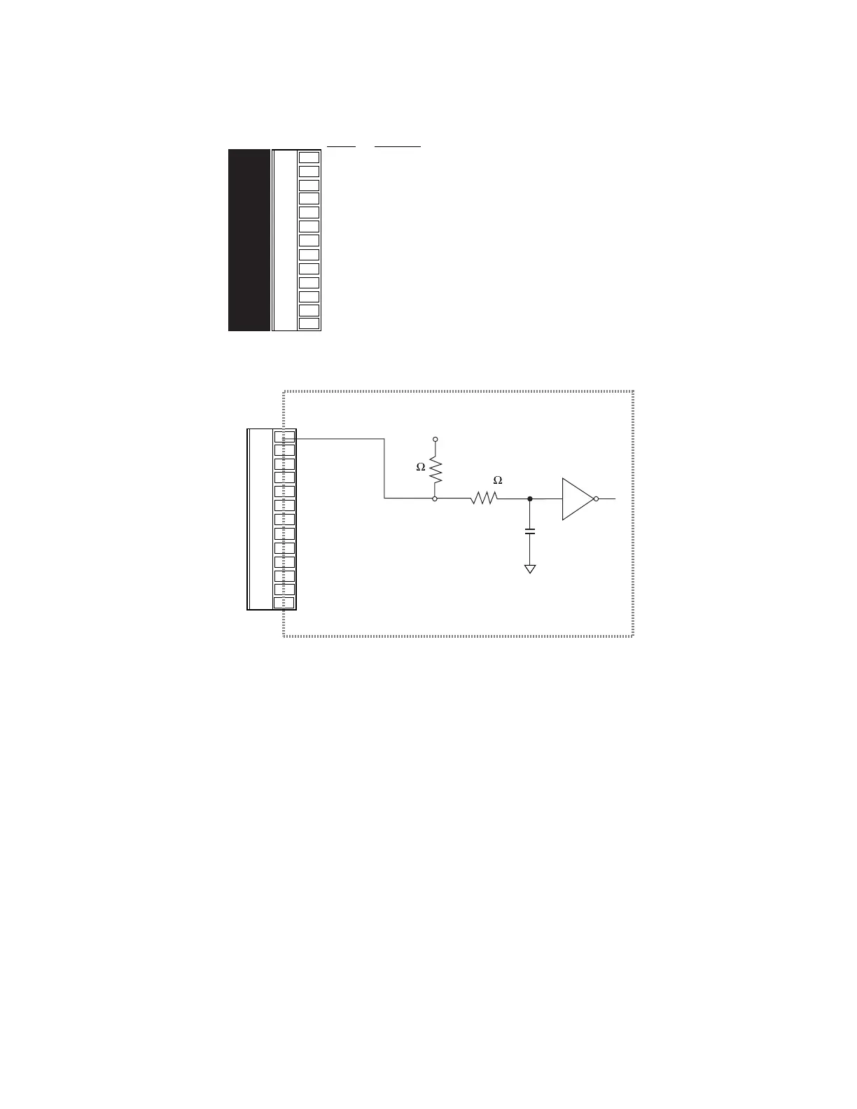
Reset Input
Internal Schematic
Reset
Gnd
NC
Enable In
Fault Out
Gnd
NC
NC
Tach Out
Gnd
+15 V
Gnd
-15 V
6.81K
+5VDC
74HC14
47.5K
1000pF
ANA GND
• Active Low: to reset drive, hold RESET input at low voltage for at least 20 milliseconds.
• Voltage Low = 1.0V maximum
• Voltage High = 3.25V – 24V
• Reset will begin when input reset signal (a low voltage) is released.
• RESET input resets drive functions; RESET command resets controller. See Recovering
From Faults in Chapter 2: Troubleshooting for more information.
Artisan Technology Group - Quality Instrumentation ... Guaranteed | (888) 88-SOURCE | www.artisantg.com

 Loading...


