Chapter 1. Installation
35
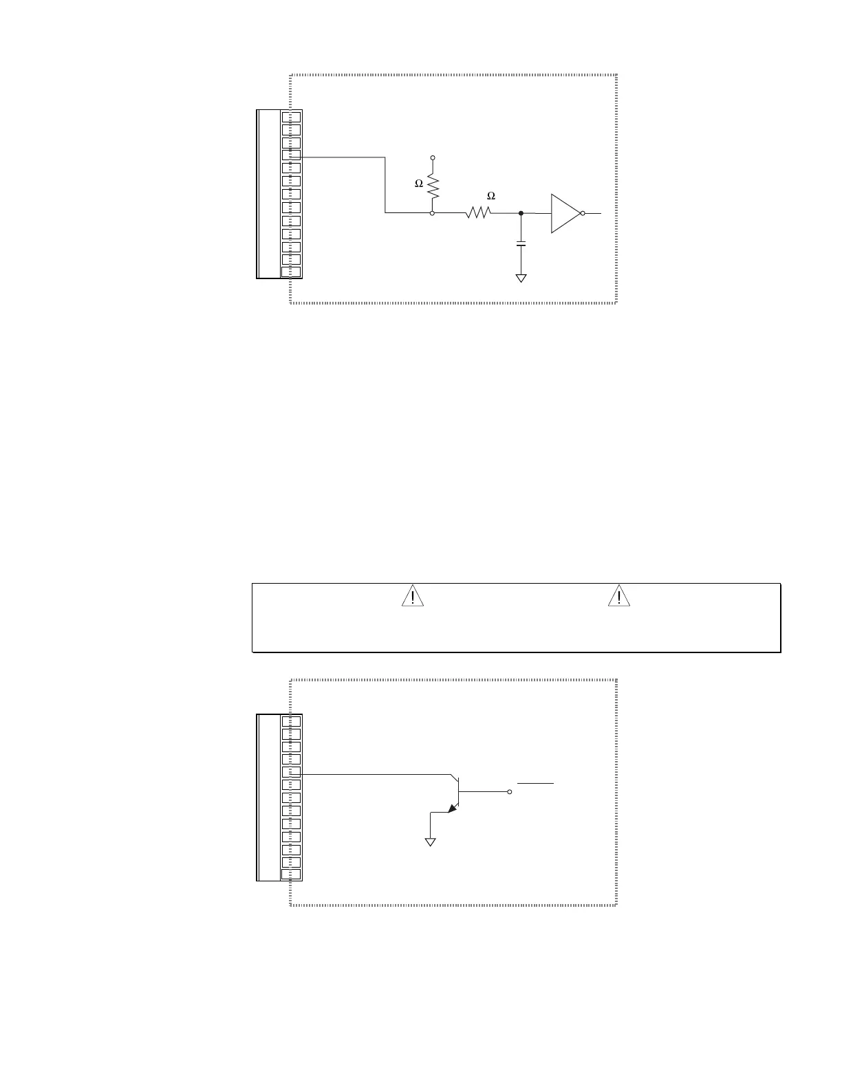
Enable Input
Internal Schematic
Reset
Gnd
NC
Enable In
Fault Out
Gnd
NC
NC
Tach Out
Gnd
+15 V
Gnd
-15 V
6.81K
+5VDC
74HC14
47.5K
1000pF
ANA GND
• Active Low: to enable the APEX615n, hold ENABLE IN at low voltage.
• Voltage Low = 1.0V maximum
• Voltage High = 3.25V – 24V
A switch wired between ENABLE IN and GND can be used as a manual disable switch.
Opening the switch disables the APX615n, which shuts down power output to the motor,
turns off the ENABLE LED, and illuminates the DISABLE LED. When the controller detects
that ENABLE IN has changed state, it issues an Immediate Kill (!K) command to stop the
program in progress. If motion is commanded while ENABLE IN is not grounded, motion will
not occur and the error message "WARNING: ENABLE INPUT INACTIVE" will appear in
the terminal emulator. See the 6000 Series Software Reference for information on commands.
Bit 6 of the TINO command (TINO.6) returns the current status of the ENABLE INPUT.
WARNING
Do not use ENABLE IN by itself as an emergency stop. The motor can freewheel when the drive
is disabled and may not stop immediately. Use a mechanical brake or some other method to
stop the motor in an emergency.
Fault Output
Fault All
BS170
Internal Schematic
Reset
Gnd
NC
Enable In
Fault Out
Gnd
NC
NC
Tach Out
Gnd
+15 V
Gnd
-15 V
ANA GND
• Active HIGH NO FAULT = Output will be low
FAULT = Output will float (go HIGH)
• Maximum Applied Voltage: 40VDC
• Maximum Current 200mA
Artisan Technology Group - Quality Instrumentation ... Guaranteed | (888) 88-SOURCE | www.artisantg.com

 Loading...


