Chapter 1. Installation
45
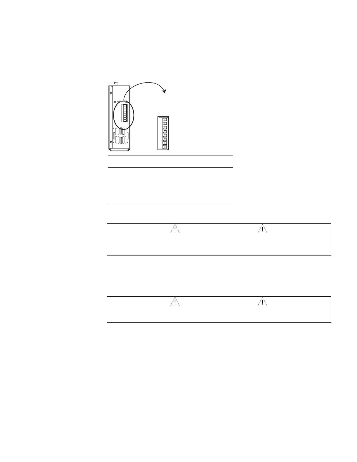
Connecting the Motor
The motor cable connects the APEX615n’s power output, located on the bottom of the drive,
to the motor's power input. APEX and SM motor cables have an MS style connector on the
end that attaches to the motor. You must wire the other end of the cable to the APEX615n’s
motor connector, which is a 8-pin removable connector located on the bottom of the cabinet.
The connector can accept wire diameters as large as 10 AWG (6 mm
2
).
Motor Connector
(Located on bottom of unit)
Shield
Motor Ground
Phase C
Phase B
Phase A
V Bus -
Regen Resistor
V Bus+
Shield
Motor Ground
Phase C
Phase B
Phase A
V Bus -
Regen Resistor
V Bus+
DANGER
HIGH VOLTAGE
Connector
Terminal
APEX Motor Cable
Wire Color
SM Motor Cable
Wire Color
Phase A Orange Red/Yellow
Phase B Blue White/Yellow
Phase C Gray Black/Yellow
Motor Ground * Green Green/Yellow
Shield * Unshielded Unshielded
* Motor Ground and Shield are connected internally to the Earth terminal on the AC power
connector
WARNING
DO NOT OMIT the Motor Ground connection. Internal failure of motor insulation can
place the motor frame at deadly potential if it is not properly grounded. Do not rely solely on
mounting bolts for motor grounding.
At this time, make no attachments to the remaining three positions on the motor connector:
V Bus+, V Bus–, Regen Resistor.
After wiring the connector to the cable, connect the motor cable to the motor and to the
APEX615n.
WARNING
The motor connector and cable produce lethal voltages. Never insert or remove the motor
cable with AC power turned on to the APEX615n.
Artisan Technology Group - Quality Instrumentation ... Guaranteed | (888) 88-SOURCE | www.artisantg.com

 Loading...


