18
APEX615n Installation Guide
Ground Connections
The APEX615n has three internal ground systems: two floating ground systems (Isolated
Ground and Analog Ground) and one Earth ground system (Chassis Ground). The table below
identifies the terminals that are associated with each ground system. Refer to the following
drawings to locate the grounding points. Note that Pin 5 on the COM 2 port serves as Iso
GND when the port is used for RS-485 communication, and serves as Shield when the port is
used for RS-232 communications (default condition).
Ground System Shared Terminals (internally connector to each other)
Isolated Ground.
Recommended for low-level
control and I/O signals.
Iso Gnd All terminals labeled “Iso Gnd”.
The "Iso Gnd" terminal on the COM 2 port when the
port is used for RS-485 communications.
I/O Gnd All even numbered pins on the 50-pin
Programmable Inputs/Outputs connector.
Analog Ground Gnd All terminals labeled “Gnd”.
Shield The “Shield” terminal on the Resolver connector only.
Chassis Ground
You must reference this ground to
earth ground by Connecting the
EARTH terminal on the AC Input
connector to the external earth
ground.
Earth The “Earth” terminal on the AC Input power connector.
(Multiple Earth terminals are provided for
convenience.)
Shield All terminals labeled “Shield” — excluding the Shield
terminal on the Resolver connector. Includes the
terminal labeled "Shld" on the COM 2 port when it is
used for RS-232 communications.
Motor Gnd “Motor Ground” terminal on the motor connector
Mounting Slot The upper right mounting slot is unpainted. You can
use a star washer with the mounting screw in this slot
to provide a grounding path from the chassis ground to
the mounting surface.
Grounding
Procedure
When you connect grounds from other devices, remember that the APEX615n’s isolated
ground (Iso GND) is not internally connected to the analog ground (GND). To prevent electrical
noise problems, the APEX615n is designed so that grounds on remote I/O devices (triggers,
RS-232C terminals, inputs and outputs, PLCs, etc.) can be kept isolated from the
APEX615n’s analog and chassis ground.
Follow the guidelines below to make ground connections in your system.
1. Only connect to
Iso GND
,
if possible.
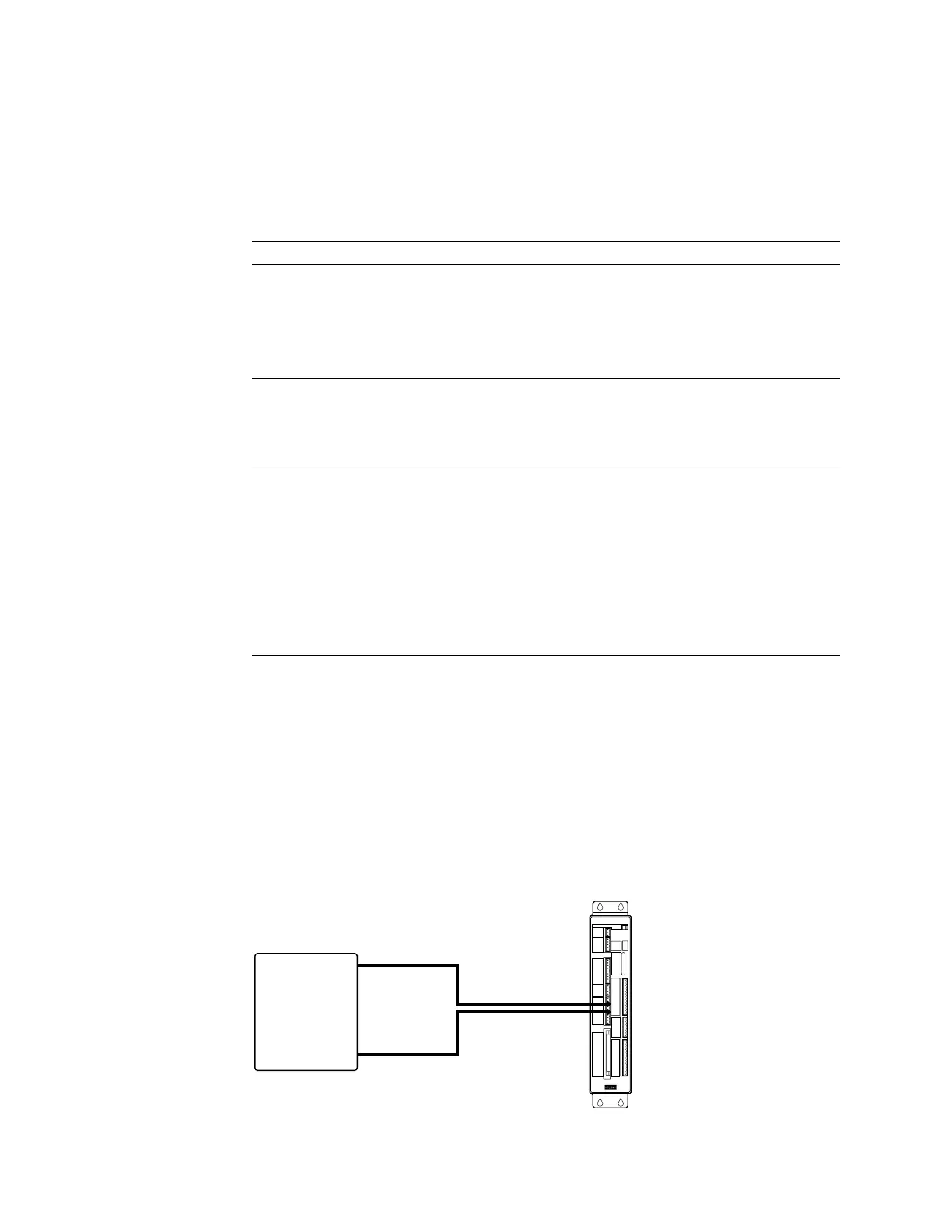
For most applications, there is no need to connect to the GND terminals. If you connect
external devices only to the left row of connectors, then make ground connections only to Iso
GND (not to GND). The next drawing shows such a connection.
Encoder Output
Auxiliary
Limits
External Encoder Input
RP 240
RS 232
Programmable Inputs/Outputs
APEX615n
Compumotor
Remote
Device
Signal
Ground
Iso Gnd
Signal
Ground Connection to Iso GND Only
Artisan Technology Group - Quality Instrumentation ... Guaranteed | (888) 88-SOURCE | www.artisantg.com

 Loading...


