28
APEX615n Installation Guide
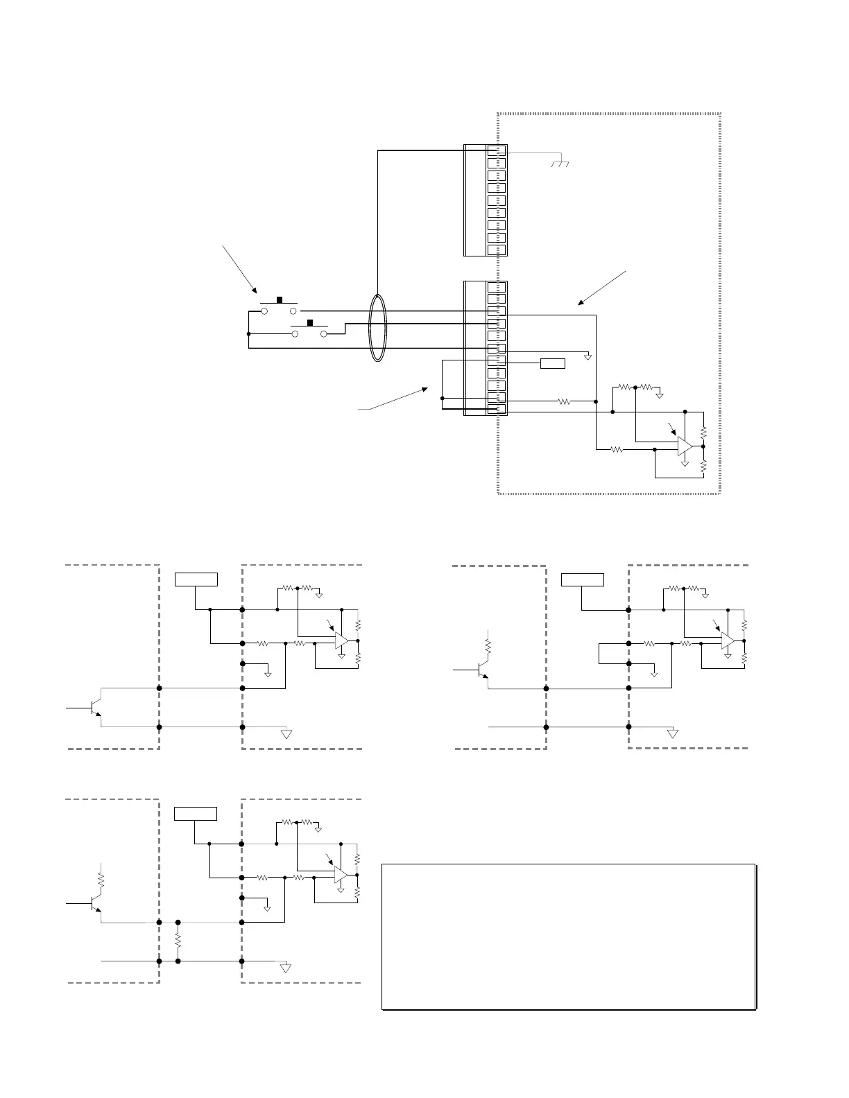
Trigger Inputs
SHLD
GND
Z-
Z+
B-
B+
A-
A+
+5V
ENCODER Connector
ANI+
ANI-
TRG-A
TRG-B
OUT-A
Iso GND
+5V
OUT-P
IN-P
AUX-P
V_I/O
6
.
8 KΩ
10
.
0 KΩ
12
.
1 KΩ
18
.
2 KΩ
20
.
0 KΩ
LM 339
31
.
6 KΩ
Isolated
Ground
+5VDC
+
-
Internal Schematic
I/O Connector
TRG-A/B connected to Iso GND
(normally-open
switches).
The active level (default is active low) can be changed with the
INLVL command.
These inputs are like the general-purpose inputs on the 50-pin
header. The differences are (1) the triggers are pulled up via
the AUX-P pull-up terminal; and (2) the triggers can be
programmed with the INFNCi-H command to function as
position capture inputs and registration inputs.
+5V connected to AUX-P and V_I/O
(sourcing current).
Provides power to the TRG input pull-up resistors. As an alternative, you can connect AUX-P
to an external power supply of up to +24VDC. TRG input switching voltage levels are determined
by V-I/O. {Low≤[1/3 x (V_I/O)] volts, High≥[2/3 x (V_I/O) ]volts } If V_I/O is connected to a +5V power
supply (internal or external), AUX-P can be connected to a supply of up to +24VDC. If V_I/O is
connected to an external +24VDC power supply, then AUX-P must also be at +24VDC (or at Iso GND).
NOTE: AUX-P is also the pull-up for the HOM, NEG & POS inputs.
SINKING CURRENT: To make the trigger inputs (and HOM, NEG & POS) sink current, connect
AUX-P to Iso GND.
CAUTION: Disconnect jumper to +5V before connecting external power supply to either IN-P, OUT-P,
AUX-P, or V_I/O.
Chassis Ground
Similar circuit for TRG-B input.
Connection to a Sinking Output Device Connection to a Sourcing Output Device
Electronic
Device
Out 5-24 Volts
Trigger Input
Connection
Output
Ground
AUX-P
The output should
be able to sink at
least 1mA of current.
ISO GND
APEX615n
ISO Ground
+
-
10
.
0 KΩ
12
.
1 KΩ
18
.
2 KΩ
20
.
0 KΩ
LM 339
6
.
8 KΩ
10
.
0 KΩ
Ground
Connection
5-24 VDC
V_I/O
Pulled up
(sourcing)
GND
External Supply
Electronic
Device
Out 5-24 Volts
Trigger Input
Connection
Output
Ground
V
1
R
1
ISO GND
Ground
Connection
5-24 VDC
AUX-P
V_I/O
APEX615n
ISO Ground
+
-
10
.
0 KΩ
12
.
1 KΩ
18
.
2 KΩ
20
.
0 KΩ
LM 339
6
.
8 KΩ
GND
10
.
0 KΩ
External Supply
Pulled
down to
ground
(sinking)
Connection to a Combination of Sinking & Sourcing Outputs
Typical value for R = 450Ω (assuming R
1
= 0)
Note: The value of R may vary depending on the value of R
1
and V
1
.
Electronic
Device
Out 5-24 Volts
Trigger Input
Connection
Output
Ground
V
1
R
1
R
ISO GND
Ground
Connection
5-24 VDC
AUX-P
V_I/O
Pulled up
(sourcing)
APEX615n
ISO Ground
+
-
10
.
0 KΩ
12
.
1 KΩ
18
.
2 KΩ
20
.
0 KΩ
LM 339
6
.
8 KΩ
GND
10
.
0 KΩ
External Supply
If you will be connecting to a combination of sourcing and sinking outputs,
connect AUX-P to +5V to accommodate sinking output devices. Then for each
individual input connected to a sourcing output, wire an external resistor between
the APEX615n's trigger input terminal and ground (see illustration). The resistor
provides a path for current to flow from the device when the output is active.
PROGRAMMING TIP
Connecting to a sinking output? Set the trigger input's active level to low
with the INLVL command (Ø = active low,
default setting
).
Connecting to a sourcing output? Set the trigger input's active level to
high with the INLVL command (1 = active high).
Thus, when the output is active, the TIN status command will report a “1”
(indicates that the input is active), regardless of the type of output that is
connected.
For details on setting the active level and checking the input status refer to the
INLVL and TIN command descriptions in the
6000 Series Software
Reference .
Artisan Technology Group - Quality Instrumentation ... Guaranteed | (888) 88-SOURCE | www.artisantg.com

 Loading...


