38
APEX615n Installation Guide
Encoder -
Quadrature Outputs
From RDC
From RDC
From RDC
CHA+
CHA -
CHB+
CHB -
CHZ+
CHZ -
Gnd
I
nternal Schematic
ENCODER OUTPUT Connector
AM26LS31
AM26LS31
AM26LS31
The APEX615n’s encoder outputs are pseudo-quadrature outputs. These quadrature outputs are
called pseudo because they are hardware–derived from resolver information and not from an
actual encoder. The resolution is 1024 counts per revolution (pre-quadrature), or 4096 counts
per revolution (post-quadrature).
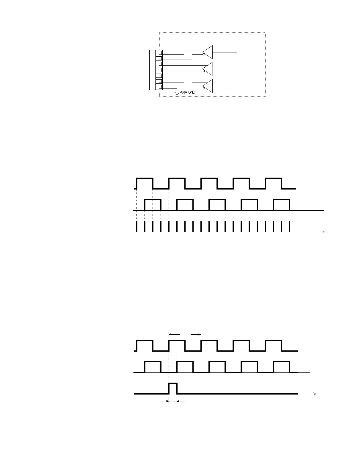
The position of the motor shaft can be determined by counting pulses. The APEX615n has a
quadrature detect circuit that enhances resolution. Channels A and B produce two square waves
that are 90 electrical degrees apart. By monitoring the rising and falling edges of CHA and
CHB, each pulse is equivalent to four counts. In this way, the 1024 counts are translated into
4096 counts, as the next figure shows.
Channel A
Channel B
Quadrature
Detect
Time
= 5 counts
= 5 counts
= 20 counts
Channel A leads Channel B
for clockwise motor shaft rotation
Direction can be determined by comparing the phase shift of Channel A relative to Channel B.
For example, if Channel A leads channel B, as shown in the previous drawing, the motor shaft
is turning in a clockwise direction.
The quadrature outputs are true differential (or complementary) outputs. The use of differential
outputs increases the system’s noise immunity. When Channel A+ goes high, Channel A-
goes low, and vice versa.
The Z Channel, or marker, provides a reference pulse once per revolution. The Z channel
outputs (CHZ+, CHZ–) are true differential, or complementary, outputs.
Channel A
Channel B
Channel Z
Width of Channel Z pulse is 90°,
relative to width of Channel A cycle.
360°
90°
Time
The width of the Z channel pulse, relative to the A channel cycle, is 90°.
Artisan Technology Group - Quality Instrumentation ... Guaranteed | (888) 88-SOURCE | www.artisantg.com

 Loading...


