Chapter 1. Installation
41
Motor Temperature
Sensor Input
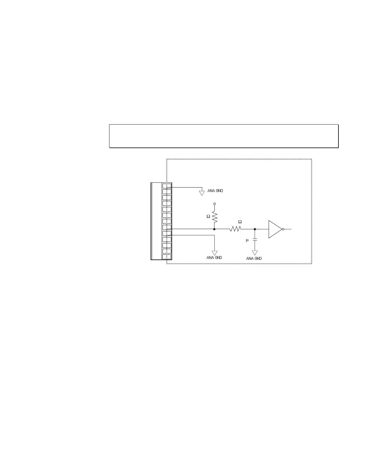
The resolver connector has two terminals through which the APEX615n can monitor motor
temperature. The terminals, labeled MT+ and MT–, should be connected to the two leads of a
normally-closed temperature sensor mounted on the motor. When the motor is within its
temperature limits, the sensor will be closed, thus shorting together MT+ and MT–. If the
motor overheats, the sensor will open. Circuit continuity will be broken, which triggers
protection circuitry in the APEX615n. It will shut down its power output, and illuminate the
red LED labeled Motor Fault.
For APEX Series motors, connect the yellow wire in the resolver cable to MT+. Connect the
orange wire to MT–. For SM Series motors, both wires are yellow; connect one to MT+ and the
other to MT-.
For other motors with normally-closed temperature sensors, connect the sensor's two wires to
MT+ and MT–.
NOTE
If your motor has no temperature sensor, use a wire to short together MT+ and MT– on the
resolver connector. The drive will not operate unless these two terminals are shorted together.
RESOLVER Connector
Internal Schematic
Shield
Red
Black
Green
Blue
Brown
White
MT+
MT -
Flt Relay+
Flt Relay -
NC
NC
10K
+5VDC
74HC14
0.1 F
10K
Artisan Technology Group - Quality Instrumentation ... Guaranteed | (888) 88-SOURCE | www.artisantg.com

 Loading...


