42
APEX615n Installation Guide
Motor Braking —
Fault Relay
Terminals
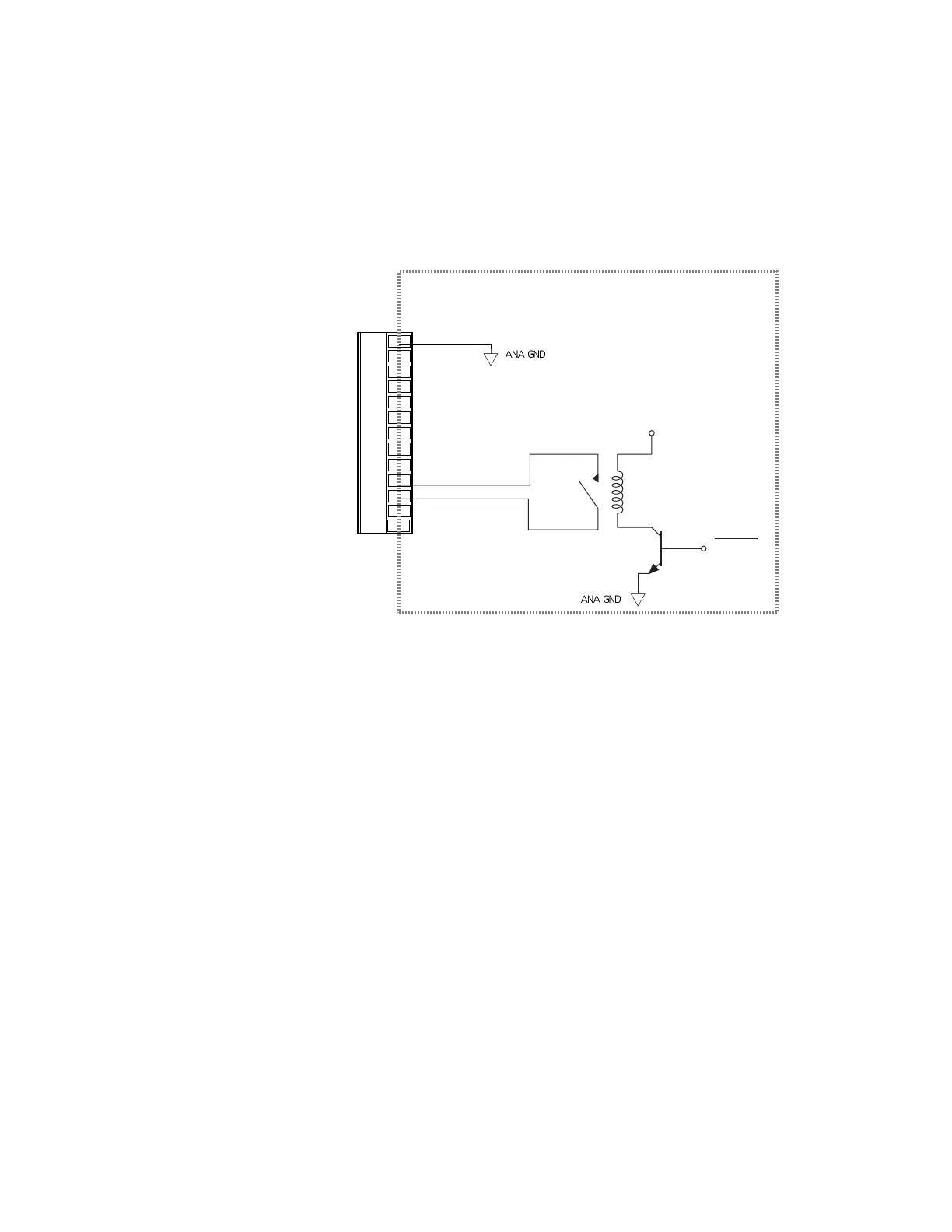
If the APEX615n faults, for any reason, the drive will be disabled and the motor will
freewheel. Refer to Chapter 2: Troubleshooting for all fault conditions. If a freewheeling load
is unacceptable, use the fault relay terminals Fault Relay+ and Fault Relay– to control a motor
brake.
The fault relay inside the APEX615n is normally open. This means that when the drive is
faulted or disabled, or when the power is off, the relay will be open. When the APEX615n is
enabled, it energizes the relay coil, and holds the relay closed. The relay is rated for 5 amps at
24VDC or 120VAC.
RESOLVER Connector
Internal Schematic
Shield
Red
Black
Green
Blue
Brown
White
MT+
MT -
Flt Relay+
Flt Relay -
NC
NC
+5VDC
Fault All
Most motor brakes have a coil that, when energized, will release the brake. To control a brake
with the fault relay terminals:
• Connect the power source for the brake to one of the fault relay terminals.
• Connect the other fault relay terminal to the brake.
• If you use a DC power source, you may need to connect a diode across the brake coil to
reduce voltage spikes when the brake is engaged or disengaged. A 1N4936 diode (or
equivalent) should be sufficient.
Artisan Technology Group - Quality Instrumentation ... Guaranteed | (888) 88-SOURCE | www.artisantg.com

 Loading...


